Digilent FX12 User Manual
Page 15
Digilent
FX12 Reference Manual
www.digilentinc.com
Copyright Digilent, Inc.
Page 15/18
Doc: 502-046
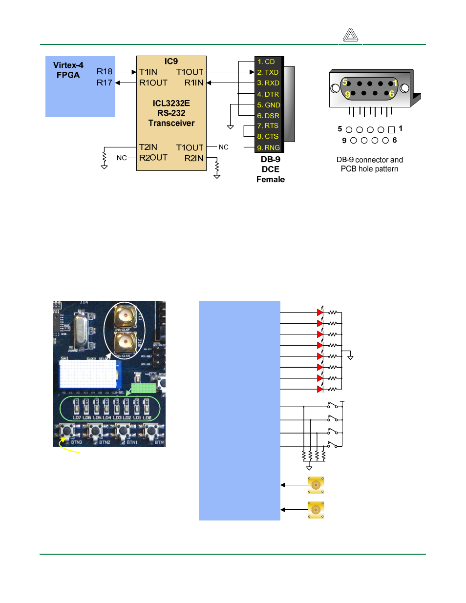
FX12 Serial Port Circuit Diagram
Other User I/O
Eight LEDs, four pushbuttons, and two SMA connectors are provided for general user I/O. Pushbutton
inputs are normally low, and they are driven high only when the pushbutton is pressed. Anodes of the
high-bright LEDs are connected to FPGA pins, so that a logic high signal will illuminate them with just
3-4mA of current. Separate LEDs are provided for power-on indication and successful completion of
FPGA configuration. The two SMA connectors provide a differential pair of I/O’s suitable for high-
frequency signals such as clocks.
SMA connectors
for (differential)
clock inputs
8 LEDs
4 Pushbuttons
Virtex-4
FPGA
LD0
LD1
LD2
LD3
LD4
LD5
T3
U3
U2
N2
P5
P4
P2
R2
LD6
LD7
BTN0
BTN1
BTN2
BTN3
SMA
Connectors
CLKP
CLKN
User
LEDs
User
Push-
buttons
T4
R5
R6
R3
R4
R1
User I/O Devices Circuit Diagram
- 410-282P-KIT (4 pages)
- 410-279P-KIT (26 pages)
- 410-258P-KIT (16 pages)
- 410-138P-KIT (28 pages)
- 410-178P-KIT (22 pages)
- 410-292P-KIT (29 pages)
- 410-274P-KIT (29 pages)
- 410-182P-KIT (22 pages)
- 410-134P-KIT (17 pages)
- 410-183P-KIT (19 pages)
- 410-155P-KIT (12 pages)
- 6015-410-001P-KIT (26 pages)
- 410-087P-KIT (164 pages)
- 410-146P-KIT (4 pages)
- 6003-410-000P-KIT (138 pages)
- XUPV2P (23 pages)
- 410-047-C2P-KIT (3 pages)
- WaveForms (85 pages)
- 410-297P-KIT (25 pages)
- 410-295P-KIT (37 pages)
- 410-296P-KIT (23 pages)
- 410-209P-KIT REV.D (16 pages)
- 410-209P-KIT REV.C (17 pages)
- 410-254P-KIT (17 pages)
- 410-280P-KIT (9 pages)
- 410-202P-KIT (20 pages)
- 410-273P-KIT (24 pages)
- 410-269P-KIT (11 pages)
- 410-216P-KIT (15 pages)
- 410-231P-KIT (4 pages)
- 410-211P-KIT (10 pages)
- 410-262P-KIT (8 pages)
- 410-229P (7 pages)
- 410-242P-KIT (4 pages)
- 6021-210-000P-KIT (27 pages)
- 410-185P-KIT (21 pages)
- 6032-410-000P-BOARD (4 pages)
- 410-174P (17 pages)
- 410-145P (6 pages)
- 210-264P-BOARD (3 pages)
- 6003-210-012P (27 pages)
- 410-236P-BOARD (2 pages)
- 410-163P (1 page)
- 410-097P-KIT (2 pages)
- 410-255P-KIT (1 page)