Digilent FX12 User Manual
Page 13
Digilent
FX12 Reference Manual
www.digilentinc.com
Copyright Digilent, Inc.
Page 13/18
Doc: 502-046
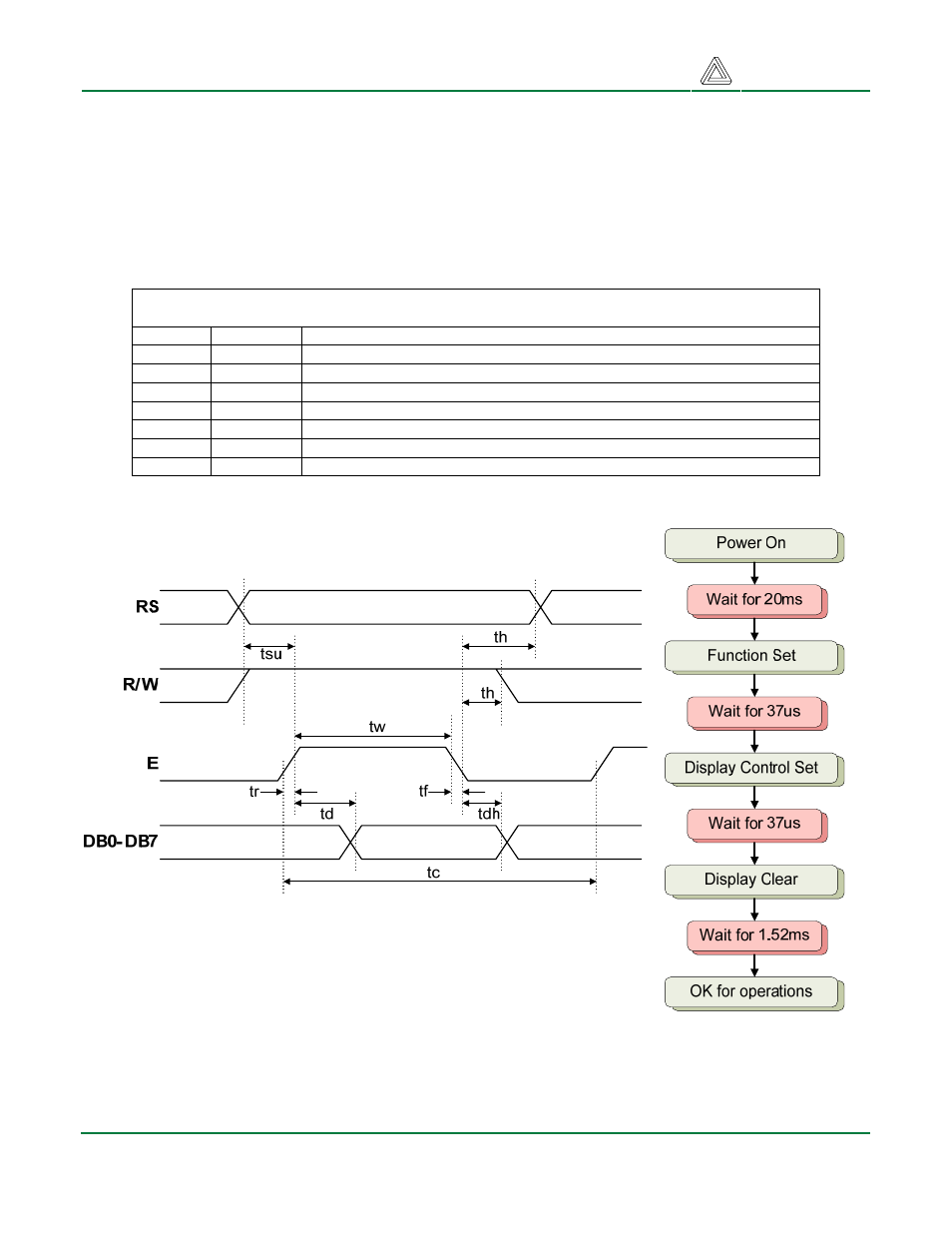
LCD Startup Sequence
A startup sequence with specific timings ensures proper LCD operation. After power-on, at least 20ms
must elapse before the function-set instruction code can be written to set the bus width, number of
lines, and character patterns (8-bit interface, 2 lines, and 5x8 dots are appropriate). After the function-
set instruction, at least 37us must elapse before the display-control instruction can be written (to turn
the display on, turn the cursor on or off, and set the cursor to blink or no blink). After another 37us, the
display-clear instruction can be issued. After another 1.52ms, the entry-mode instruction can set
address increment (or address decrement) mode, and display shift mode (on or off). After this
sequence, data can be written into the DDRAM to cause information to appear on the display.
LCD Connector Signals
Pin No.
Symbol
Signal Description
1 Vss Signal
ground
2
Vdd
Power supply (5V)
3
Vo
Operating (contrast) voltage (LCD drive, typically 100mV at 20C)
4
RS
Register select: high for data transfer, low for instruction register
5
R/W
Read/write signal: high for read mode, low for write mode
6
E
Read/write strobe: high for read OE; falling edge writes data
7-14
Data Bus
Bidirectional data bus
LCD Read Cycle