16 built-in self-test – Digilent 410-274P-KIT User Manual
Page 29
Nexys4™ FPGA Board Reference Manual
Copyright Digilent, Inc. All rights reserved.
Other product and company names mentioned may be trademarks of their respective owners.
Page 29 of 29
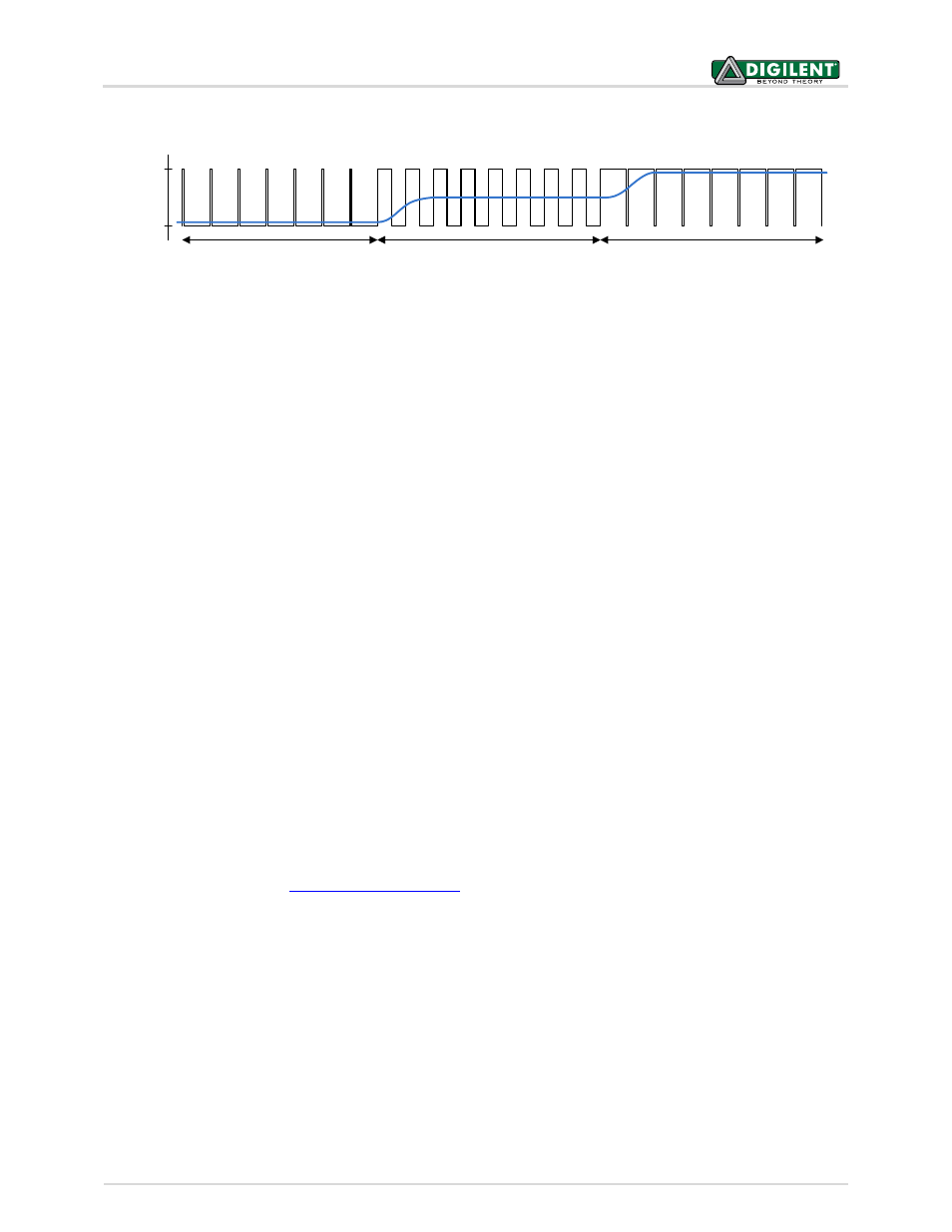
10% Duty Cycle
50% Duty Cycle
90% Duty Cycle
Vdd
Gnd
PWMA = 0.1·Vdd
PWMA = 0.5·Vdd
PWMA = 0.9·Vdd
16 Built-In Self-Test
A demonstration configuration is loaded into the SPI Flash device on the Nexys4 board during manufacturing. The
source code and prebuilt bitstream for this design are available for download from the Digilent website. If the
demo configuration is present in the SPI Flash device and the Nexys4 board is powered on in SPI mode, the demo
project will allow basic hardware verification. Here is an overview of how this demo drives the different onboard
components:
The user LEDs are illuminated when the corresponding user switch is placed in the on position.
The tri-color LEDs are controlled by some of the user buttons. Pressing BTNL, BTNC, or BTNR causes them
to illuminate either red, green or blue, respectively. Pressing BTND causes them to begin cycling through
many colors. Repeatedly pressing BTND will turn the two LEDs on or off.
Pressing BTNU will trigger a 5 second recording from the onboard PDM microphone. This recording is then
immediately played back on the mono audio out port. The status of the recording and playback is
displayed on the user LEDs.
The VGA port displays feedback from the onboard microphone, temperature sensors, accelerometer, RGB
LEDs, and USB Mouse.
Connecting a mouse to the USB-HID Mouse port will allow the pointer on the VGA display to be
controlled. Note that some Microsoft mice have difficulty communicating with this demo.
On power-up, the seven-segment display will show the results of an automated test for the onboard
CellRAM, accelerometer, and temperature sensor. It will then display a moving snake pattern. Note that
the accelerometer test will fail if the board is on an unstable or un-level surface when it is powered on,
and the temperature sensor test may fail if the board is in an extreme thermal climate. With these two
considerations in mind, if your board is reporting a failure, make note of the error code and contact
Digilent support at
All Nexys4 boards are 100% tested during the manufacturing process. If any device on the Nexys4 board fails test
or is not responding properly, it is likely that damage occurred during transport or during use. Typical damage
includes stressed solder joints and contaminants in switches and buttons resulting in intermittent failures. Stressed
solder joints can be repaired by reheating and reflowing solder and contaminants can be cleaned with off-the-shelf
electronics cleaning products. If a board fails test within the warranty period, it will be replaced at no cost. Contact
Digilent for more details.
Figure 32. Representation of a PWM integrator producing an output voltage by integrating the pulse train