1 vga system timing – Digilent 410-274P-KIT User Manual
Page 14
Nexys4™ FPGA Board Reference Manual
Copyright Digilent, Inc. All rights reserved.
Other product and company names mentioned may be trademarks of their respective owners.
Page 14 of 29
8.1 VGA System Timing
VGA signal timings are specified, published, copyrighted, and sold by the VESA organization (www.vesa.org). The
following VGA system timing information is provided as an example of how a VGA monitor might be driven in 640
by 480 mode.
NOTE: For more precise information, or for information on other VGA frequencies, refer to documentation
available at the VESA website.
CRT-based VGA displays use amplitude-modulated moving electron beams (or cathode rays) to display information
on a phosphor-coated screen. LCD displays use an array of switches that can impose a voltage across a small
amount of liquid crystal, thereby changing light permittivity through the crystal on a pixel-by-pixel basis. Although
the following description is limited to CRT displays, LCD displays have evolved to use the same signal timings as
CRT displays (so the “signals” discussion below pertains to both CRTs and LCDs). Color CRT displays use three
electron beams (one for red, one for blue, and one for green) to energize the phosphor that coats the inner side of
the display end of a cathode ray tube (see Fig 12).
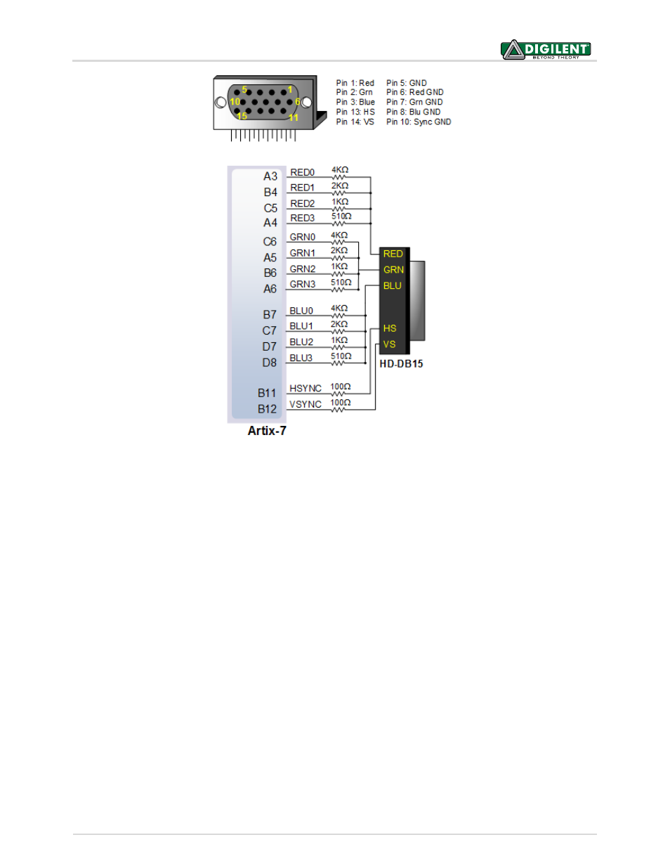
Figure 11. Nexys4 VGA Interface