14 microphone, 1 pulse density modulation (pdm) – Digilent 410-274P-KIT User Manual
Page 25
Nexys4™ FPGA Board Reference Manual
Copyright Digilent, Inc. All rights reserved.
Other product and company names mentioned may be trademarks of their respective owners.
Page 25 of 29
14 Microphone
The Nexys4 board includes an omnidirectional MEMS microphone. The microphone uses an Analog Device
ADMP421 chip which has a high signal to noise ratio (SNR) of 61dBA and high sensitivity of -26 dBFS. It also has a
flat frequency response ranging from 100Hz to 15kHz. The digitized audio is output in the pulse density modulated
(PDM) format.
The component architecture is shown in Figure 24.
Artix 7
ADMP421
CLK
DATA
L/R SEL
J5
H5
F5
Microphone
CLK: Clock Input to Microphone
DATA: Data Output Signal
L/R SEL: Left/Right Channel Select
14.1 Pulse Density Modulation (PDM)
PDM data connections are becoming more and more popular in portable audio applications, such as cellphones
and tablets. With PDM, two channels can be transmitted with only two wires. The frequency of a PDM signal
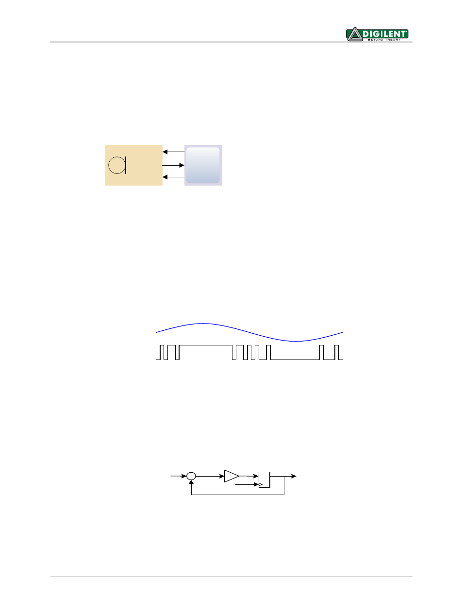
usually falls in the range of 1MHz to 3MHz. In a PDM bit stream, a 1 corresponds a positive pulse and a 0
corresponds a negative pulse. A run consisting of all ‘1’s would corresponds to the maximum positive value and a
run of ‘0’s would corresponds to the minimum amplitude value. Figure 25 shows how a sine wave is represented in
PDM signal.
0101101111111111111101101010010000000000000100010
Sine Wave
PDM Signal
A PDM signal is generated from an analog signal through a process called Delta-Sigma Modulation. A simple
idealized circuit of Delta-Sigma Modulator is shown as Figure 26.
Integral
-
+
PDM
Analog
clk
Flip-Flop
Figure 24. Microphone Block Diagaram
Figure 25. PDM representation of a sine wave
Figure 26. Simple Delta-Sigma Modulator Circuit