15 mono audio output – Digilent 410-274P-KIT User Manual
Page 27
Nexys4™ FPGA Board Reference Manual
Copyright Digilent, Inc. All rights reserved.
Other product and company names mentioned may be trademarks of their respective owners.
Page 27 of 29
128 Samples
53.3ns
128 Samples
128 Samples
Counter 1 Counting
Counter 1
Counting
Counter 2 Counting
41.6ns
0.416ns
83.2ns
Clock
Data
0 1 ... 0 1 1
0 1 1
0 1 1
0 1 1
...
...
...
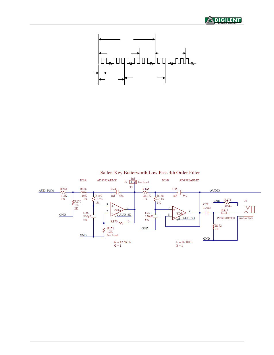
15 Mono Audio Output
The on-board audio jack (J8) is driven by a Sallen-Key Butterworth Low-pass 4
th
Order Filter that provides mono
audio output. The circuit of the low pass filter is shown in Fig 29. The input of the filter (AUD_PWM) is connected
to the FPGA pin A11. A digital input will typically be a pulse width modulated (PWM) signal or pulse density
modulated (PDM) signal produced by the FPGA. The low pass filter on the input will act as a reconstruction filter to
convert the pulse width modulated digital signal into an analog voltage on the audio jack output.
The frequency response of SK Butterworth Low Pass Filter is shown in Fig 30. The AC analysis of the circuit is done
using NI Multism 12.0.
Figure 28. Sampling PDM with two counters
Figure 29. Sallen-Key Butterworth Low Pass 4
th
Order Fliter