2 microphone digital interface timing – Digilent 410-274P-KIT User Manual
Page 26
Nexys4™ FPGA Board Reference Manual
Copyright Digilent, Inc. All rights reserved.
Other product and company names mentioned may be trademarks of their respective owners.
Page 26 of 29
Sum
Integrator Out
Flip-flop Output
0.4-0=0.4
0+0.4=0.4
0
0.4-0=0.4
0.4+0.4=0.8
1
0.4-1=-0.6
0.8-0.6=0.2
0
0.4-0=0.4
0.2+0.4=0.6
1
0.4-1=-0.6
0.6-0.6=0
0
0.4-0=0.4
0+0.4=0.4
0
0.4-0=0.4
0.4+0.4=0.8
1
0.4-1=-0.6
0.8-0.6=0.2
0
To keep things simple here, assume that the analog input and digital output have the same voltage range 0~Vdd.
The input of the flip-flop acts like a comparator (any signal above Vdd/2 is considered as ‘1’ and any input bellow
Vdd/2 is considered ‘0’). The input of the integral circuit is the difference of the input analog signal and the PDM
signal of the previous clock cycle. Then the integral circuit integrates both these inputs, and the output of the
integral circuit is sampled by a D-Flip-flop. Table 7 shows the function of the delta-sigma modulator with an input
of 0.4Vdd.
Note that the average of the flip-flop output equals the value of the input analog signal. So, in order to get the
value of analog input, all that is needed is a counter that counts the ‘1’s for a certain period of time.
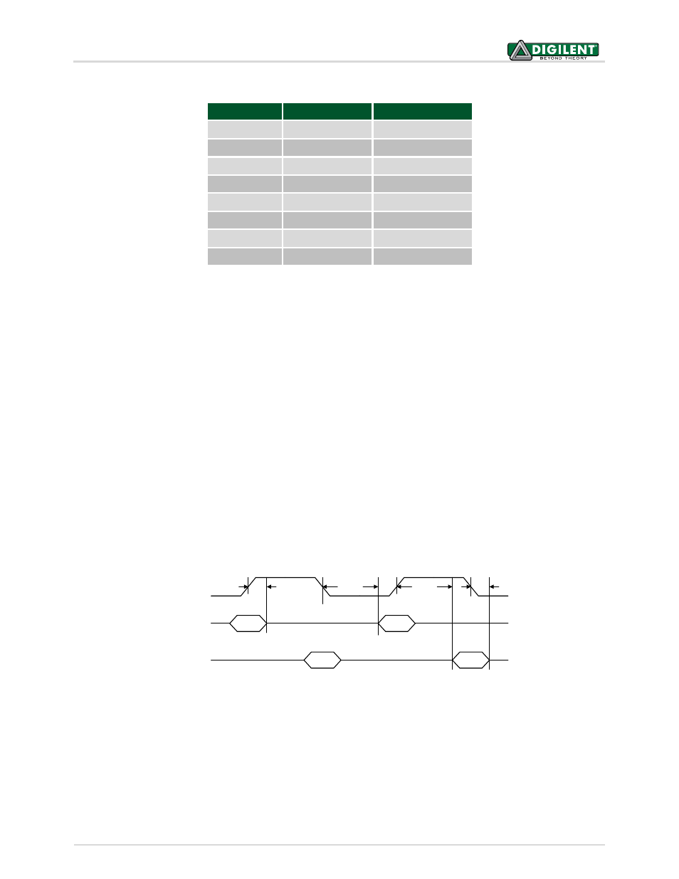
14.2 Microphone Digital Interface Timing
The clock input of the microphone can range from 1MHz to 3.3MHz based on the sampling rate and data precision
requirement of the applications. The L/R Select signal must be set to a valid level, depending on which edge of the
clock the data bit will be read. A low level on L/RSEL makes data available on the rising edge of the clock, while a
high level corresponds to the falling edge of the clock, as shown in Fig 27.
Pulse
Pulse
Pulse
Pulse
CLK
DATA1
DATA2
< 20 ns
> 30 ns
> 30 ns
< 20 ns
The typical value of the clock frequency is 2.4MHz. Assuming that the application requires 7-bit precision and
24KHz, there can be two counters that count 128 samples at 12KHz, as shown in Fig 28.
Table 7. Sigma Delta Modulator with a 0.4Vdd input
Figure 27. PDM Timing Diagram