Mount the es8508 – Comtrol ES8508 Series User Guide User Manual
Page 11
RocketLinx ES8508 Series User Guide: 2000575 Rev. A
Mount the ES8508 - 11
Hardware Installation
Digital output relay contacts are energized (open) for normal operation and close for fault conditions. The
digital output relay contacts support up to 1A at 30VDC. Do not apply voltage and current higher than the
specifications.
1.
Insert the positive and negative wires (12-24 AWG) into V+ and V-.
2.
Tighten the wire-clamp screws to prevent the wires from coming loose.
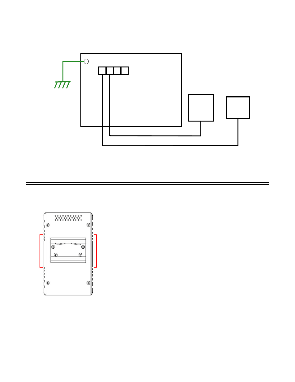
Mount the ES8508
You can use the following procedure to mount the ES8508 on a DIN raill.
The DIN rail clip is already attached to the ES8508. If the DIN rail clip is not screwed onto the ES8508, follow
the instructions and the figure below to attach DIN rail clip to the ES8508.
- +
Power
Source
DO1
DI1
- +
Buzzer/
PLC
Input
+
Earth Ground
24VDC/1A
Digital Output
Relay Output
1.
If necessary, use the screws to attach DIN rail clip to the rear
panel of the ES8508. (To remove DIN rail clip, reverse Step 1.)
2.
Insert the upper end of DIN rail clip into the back of DIN rail
track from its upper side.
3.
Lightly push the bottom of DIN rail clip into the track.
4.
Verify that the DIN rail clip is tightly attached on the track.
5.
To remove the ES8508 from the track, reverse the steps above.
DIN Rail Mounting