Connect the digital input and relay outputs – Comtrol ES8508 Series User Guide User Manual
Page 10
10 - Connect the Digital Input and Relay Outputs
RocketLinx ES8508 Series User Guide: 2000575 Rev. A
Hardware Installation
b.
Tighten the wire-clamp screws to prevent the wires from coming loose.
• PWR1 and PWR2 support power redundancy and reverse polarity protection.
• If both power inputs are connected, the ES8508 is powered from the highest connected voltage.
• The ES8508 can emit an alarm if PW1 or PW2 are no longer receiving power. See the
discussion on
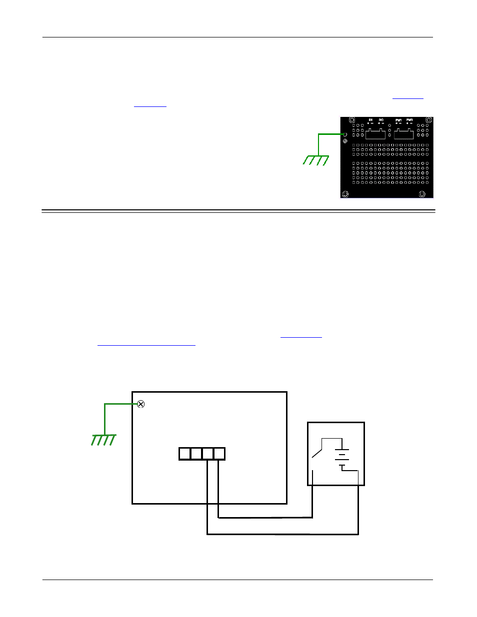
2.
Connect a ground wire between the chassis and earth ground using
12-24AWG wire to ensure that the ES8508 is not damaged by noise
or electrical shock.
a.
Loosen the earth ground screw on the bottom of the ES8508.
b.
Insert the ground wire.
c.
Tighten the ground screw after the earth ground wire is
connected.
Connect the Digital Input and Relay Outputs
The ES8508 provides one digital input and one digital output (dry relay output) on the terminal block
connectors on the bottom of the unit. The fault conditions can be configured in the web user interface or
Command Line Interface (CLI) and include:
•
Power Failure
•
Port Link
•
Ring
•
Ping
•
Ping Reset
•
Dry output
•
DI
You can configure events using one of the ES8508 user interfaces (
on Page 116) or the Command
Line Interface (
The Digital Input pin can be pulled high or low so that the connected equipment can actively drive these pins.
The web user interface allows you to read and set the value to the connected device. The power input voltage
of logic low is 0 to 10VDC and logic high is 11 to 30VDC. Do not apply a higher voltage than the specification;
it may cause internal circuit damage or a cause an incorrect DI action.
- +
DO
DI1
- +
Earth
Sensor
Sensor
1 = High Output: 11-30VDC
0 = Low Output: 0-10VDC
Digital Input