Carrier 42V User Manual
Page 56
56
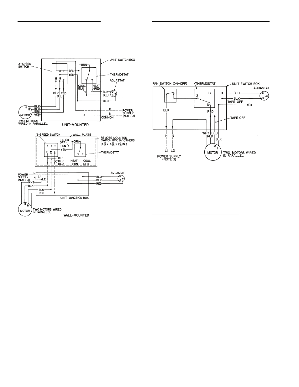
Thermostatic Fan Control, 2-Pipe Systems — The thermo-
stat cycles the fan on and off from any selected speed setting to
maintain selected room temperature. Controls can be wired for
heating-only, cooling-only or for heating/cooling by the addi-
tion of an automatic changeover device that senses water tem-
perature and changes the action of the thermostat as required.
See Fig. 51.
Thermostatic Fan Control, 2-Pipe System with Safety
Cycle — This control is used for high humidity situations in
which condensate problems can occur if fan is turned off while
chilled water is still running through the coil.
The wiring provides fan cycling from HIGH to LOW on the
cooling cycle and from LOW to OFF on the heating cycle. An
ON-OFF toggle switch replaces the standard 3-speed fan
switch. The toggle switch can be concealed to ensure that the
unit runs on low speed when cooling. This action greatly
reduces the chance of condensation problems that exist with
other standard fan cycling controls. See Fig. 52.
Thermostatic Electric Valve Control, 2-Pipe — A thermo-
statically controlled 2-position valve provides superior control
to fan cycling. With this control, the fan runs continuously un-
less it is manually switched to the OFF position. The fan must
be on before the valve can be opened to supply water to the
coil.
This system can be used for normal 2-pipe changeover
systems and can also be furnished for cooling-only or heating-
only applications by omitting the changeover and specifying
which application is intended. See Fig. 53 and 54 for line volt-
age control. See Fig. 55 and 56 for 24-v control.
Fig. 51 — Thermostatic Fan Control
(2-Pipe System)
NOTES:
1. Motors are thermally protected.
2. Use copper conductors only.
3. See unit nameplate for power supply. Provide disconnect
means and overload protection as required.
4. Unit-mounted thermostats are not recommended for fan control
because of poor temperature sensing. Fan control not available
on 42VC,VE lowboy units.
Fig. 52 — Thermostatic Fan Control
(2-Pipe System with Safety Cycle)
NOTES:
1. Motors are thermally protected.
2. Use copper conductors only.
3. See unit nameplate for power supply. Provide disconnect
means and overload protection as required.