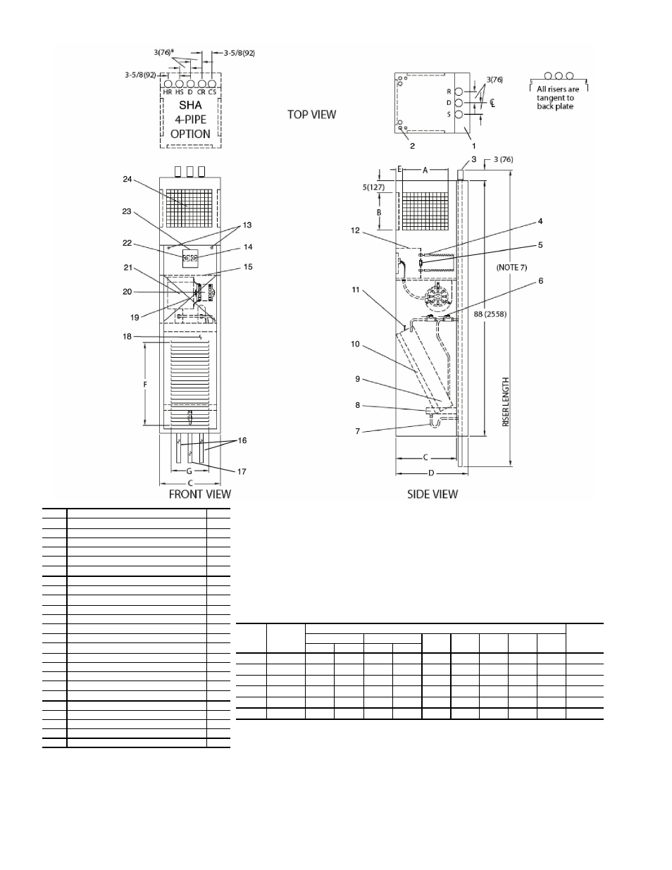
Fig. 29 — 42sh cabinet dimensions – Carrier 42V User Manual
Page 32
32
†Unit weights are based on dry coils and minimum rows. Weights exclude packaging, valves, and other components.
UNIT
SIZE
NOM
AIRFLOW
(cfm)
DIMENSIONS (in.)
UNIT
WEIGHT†
(lb)
Single Supply
Double Supply
C
D
E
F
G
A
B
A
B
03
300
14
8
14
6
17
22
3
/
8
1
1
/
2
22
1
/
8
14
3
/
4
202
04
400
14
12
14
8
17
22
3
/
8
1
1
/
2
22
1
/
8
14
3
/
4
247
06
600
14
12
14
8
20
25
3
/
8
2
26
5
/
8
17
3
/
4
262
08
800
14
16
14
10
20
25
3
/
8
2
26
5
/
8
17
3
/
4
286
10
1000
18
16
14
12
24
29
3
/
8
3
31
1
/
8
17
3
/
4
311
12
1200
18
16
14
12
24
29
3
/
8
3
31
1
/
8
17
3
/
4
336
*Drawing provided for reference only. Dimensions may vary with options ordered.
NOTES:
1.
Units are fabricated of 18-gage galvanized steel with a 16-gage galvanized fan deck, painted with Arctic White.
2.
3-speed switch and thermostat are unit mounted.
3.
Risers are piped to coil with valves as specified.
4.
Blower, motor, valves, coil, and filter are accessible through the return air opening.
5.
Unit is insulated with coated fiberglass.
6.
Control box is insulated with
1
/
2
-in. insulation for unit mounted controls.
7.
Riser length = [(floor to floor) +2 in.], maximum riser length = 115 inches.
8.
Maximum riser size is 2
1
/
2
-in. diameter. If larger sizes are required, please consult the factory.
9.
Expansion loops in hot water heating circuits as required.
10.
A 9-in. x 2
1
/
4
-in. slot is provided in the inside back panel for coil connection penetration to permit expansion and
contraction of risers. Care must be taken to position the risers so that coil connection is at center of slot.
11.
Drawing is pictorial (see unit arrangements for actual supply and return air orientation).
12.
42SHA available in front return only.
13.
All dimensions are in inches.
A42-4126
**Factory-Installed.
††Field-Installed.
ITEM
DESCRIPTION
QTY
1
Full Riser Chase
1
2
Electrical Knockouts
1
3
3-in. Expansion Section
3/5
4
Strip Heater (Optional)
1
5
Limit Switch**†† (Optional)
1
6
1
/
2
-in. Isolation Ball Valves**
2/4
7
Flexible Drain Tube/P-Trap
1
8
Drain Pan
1
9
Coil
1
/
2
-in. OD Tube
1
10
Filter, Throwaway, 1-in.**
1
11
Air Vent, Manual
1
12
Control Box
1
13
Cabinet Camloc
®
Fasteners
2
14
3-Speed Switch
1
15
Electrical Access Panel
1
16
Riser, Supply and Return (Copper)
2/4
17
Riser, Drain (Copper)
1
18
Return Air Panel
1
19
Return Air Blockoff Panel (Optional)
1
20
Motor, 3-Speed, PSC
1
21
Blower
1
22
Thermostat
1
23
Hinged Control Access Door
1
24
Double Deflection Steel Core Grille Assembly
1
LEGEND
CR —
Cold Water Return
CS —
Cold Water Supply
D
—
Drain
HR —
Hot Water Return
HS —
Hot Water Supply
R
—
Return
S
—
Supply
Fig. 29 — 42SH Cabinet Dimensions