1. tu-7 tone unit, Tm-3530a/2570a/2550a/2530a, Only) – Kenwood TM-3530A User Manual
Page 40: Optional accessories
Attention! The text in this document has been recognized automatically. To view the original document, you can use the "Original mode".
7. OPTIONAL ACCESSORIES
The following accessories are available for more sophisticated operation of your transceiver.
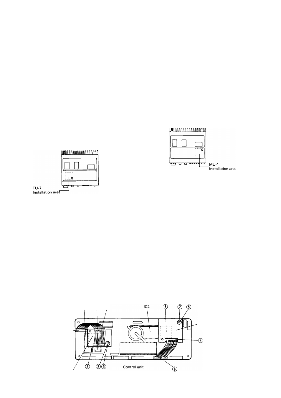
7-2. MU-1 MODEM UNIT
7-1. TU-7 TONE UNIT
(TM-3530A/2570A/2550A/2530A
only)
38 CTCSS tone frequencies can be selected from the
front panel of the radio by using the TONE FREQUENCY
selector. The selected tone is displayed in the LCD dis
play.
Accessories:
1. Hexagonal boss..................... (J32-0791-05)...... 1 pc.
2. Machine screw...................... (N35-2604-41)...... 2 pcs.
3. Cable assembly.....................(E31-3150-05)...... 1 pc.
4. Foam spacer.........................(G13-0826-04)...... 1 pc.
5. Instruction manual............(850-8045-10).......... 1 copy
Installation procedure
Caution:
Before installation be sure to disconnect the power cable,
or damage may result to the radio or tone unit.
© Remove the four screws securing the bottom cover.
© Remove the machine screw near IC5 on the control
unit (X53-1440-10) and replace it with the hexagonal
boss.
© Remove the backing from one side of the foam spacer
and install the spacer on top of IC5 and IC6, as shown
by the dotted line in the figure.
© Connect the cable assembly to the TU-7 tone unit.
© Remove the remaining backing from the foam spacer.
Position the tone unit as shown and secure it to the
chassis with the supplied machine screw.
Note; Only one screw is needed.
© Connect the cable assembly to the control unit as
shown in the figure.
For details on operation of the TU-7 subaudible tone en
coder please refer to section 4-6-2 on page 20.
* The output level of the tone encoder has been factory
adjusted, and should not require further adjustment.
IC6 IC5 0
Installation of the MU-1 unit permits the DCL system
operation.
Accessories:
1. Hexagonal boss............... (J32-0791-04)........... 1 pc.
2. Machine screw................. (N35-2604-41)...........2 pcs.
3. Cable assembly................(E31-31 51-05)..........1 pc.
4. Foam spacer.................... (G1 3-0826-04)......... 1 pc.
5. Instruction manual............(850-8046-10)........... 1 copy
Installation procedure
Caution:
Before installation, be sure to unplug the power cable, or
damage may result to the radio or modem unit.
(D-
© Remove the four black screws securing the bottom
cover.
© Remove the machine screw in the right rear corner of
the control unit (X53-1440-10), and install the hexa
gonal boss in its place.
© Remove the backing from one side of the foam spacer
and install the spacer on the right end of IC2, as
shown by the dotted line in the figure.
® Connect the cable assembly to the MU-1 modem unit.
© Remove the remaining backing from the foam spacer.
Place the MU-1 unit as shown in the figure and secure
it with the supplied machine screw. (Note only one
screw is needed.)
© Connect the cable assembly to the control unit as
shown in the figure.
© Reinstall the bottom cover to complete the installa
tion.
For details on operation of the DCL system please refer
to section 4-8 "DCL SYSTEM" on page 23.
* If the modem unit (MU-1) is not installed you will be
able to program the DCL system, but no DCL signals
will be transmitted or decoded.
MU-1
Modem unit
TU-7
Tone unit
40