Kenwood TM-3530A User Manual
Page 12
Attention! The text in this document has been recognized automatically. To view the original document, you can use the "Original mode".
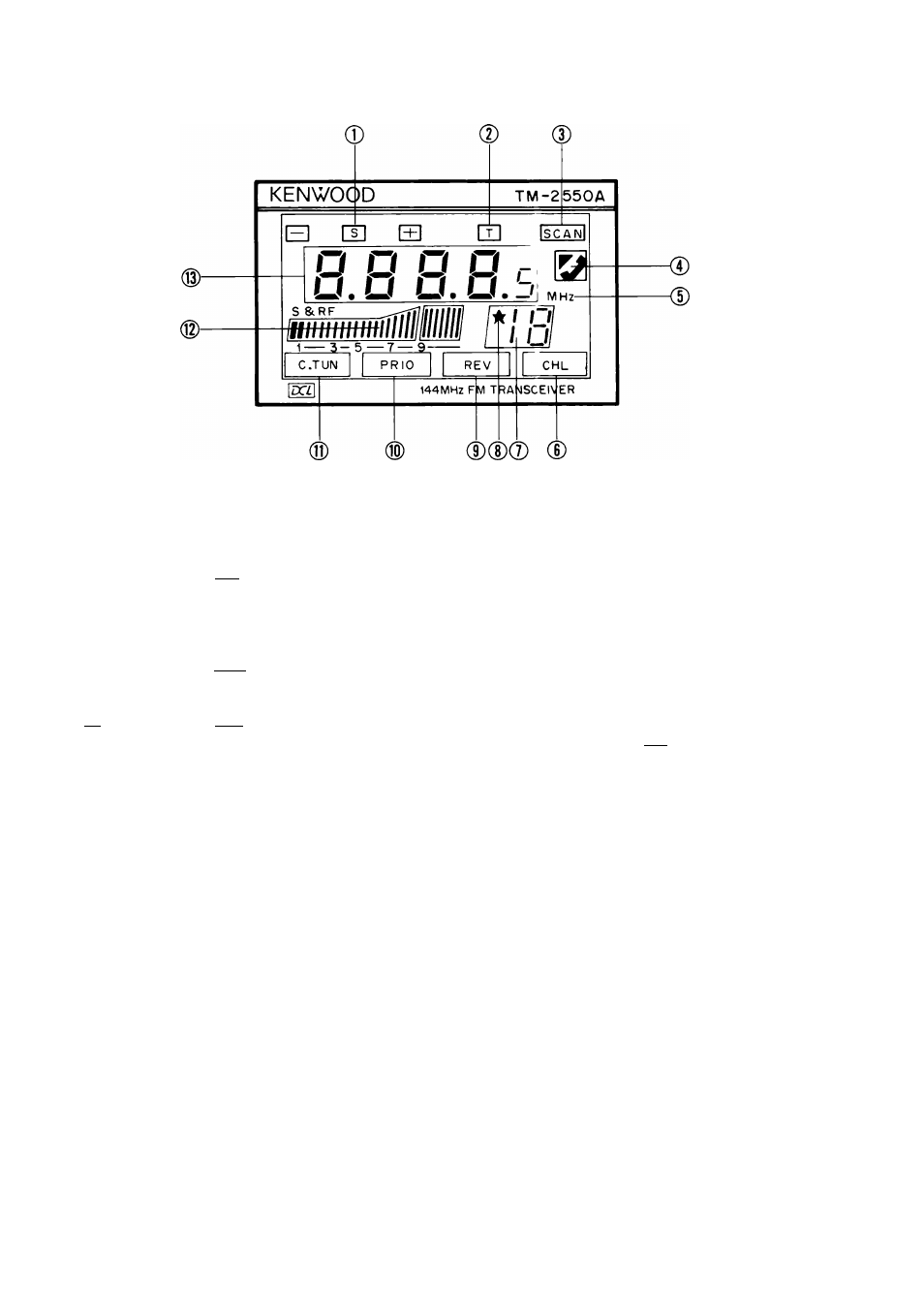
1. LCD group
© TX offset indicators
Q By pressing the |0S| key on the keyboard, the 0
indicator will light in sequence to show the trans
mit frequency is switched down 600 kHz (1.6
MHz with the TM-3530A) from the receive fre
quency.
By pressing the [OS | key on the keyboard, the
indicator will light in sequence to show the trans
ceiver is operating in the simplex mode.
[T] By pressing the |OS| key on the keyboard, the Q
indicator will light in sequence to show the trans
mit frequency is switched up 600 kHz (1.6 MHz
with the TM-3530A) from the receive frequency.
© [T1 indicator
This lights when the tone function has been selected.
© SCAN indicator
This indicator lights when scan operation is in pro
gress.
© TELEPHONE indicator
This indicator lights when the automatic telephone
number transmission function has been selected. See
page
21.
(With
TM-3530A/2570A/2550A/2530A
only)
© Hz indicator
"MHz" lights in the frequency display mode.
[The display changes to "Hz" in the tone frequency
display
mode.
(TM-3530A/2570A/2550A/2530A
only)]
© CHL (Channel Link) indicator
This indicator lights when the DCL (Digital Channel
Link) has been completed.
© Memory channel display indicator
These indicators display memory channels 1 to 19, A
( R ) , b ( b ) , d ( d ) o r U ( u ' ) .
© ★ mark
Memory channel scan lock-out designator.
If you desire to skip a busy memory channel during
memory scan, press the |L0| key. The star designates
the channel will be skipped during scan.
© REV (Reverse) indicator
This indicator lights when the REV switch is ON.
PRIO (Priority) indicator
This indicator lights when the PRIO switch is ON.
(S)
C.TUN (Center Tuning) indicator
This indicator lights when the receiver has tuned in to
another station.
dD S/RF level meter
This LED level meter indicates the relative receive in
put signal strength or transmit RF output.
The level meter also indicates the microphone input
level during low-power transmission so that micro
phone checking is possible.
(ID
Frequency, digital code, and call sign (ASCII code) in
formation are displayed.
[The tone frequency, telephone channel number and
telephone
number
are
also
displayed.
(With
TM-3530A/2570A/2550A/2530A only)]
12