6. adjustments, 6-2. low power output, 6-3. microphone gain – Kenwood TM-3530A User Manual
Page 34: 6-4. dtmf level, 6-5. sidetone and beeper level, 6-6. rf power meter, Low power output, Microphone gain, Dtmf level, Sidetone and beeper level
Attention! The text in this document has been recognized automatically. To view the original document, you can use the "Original mode".
5-6. ADJUSTMENTS
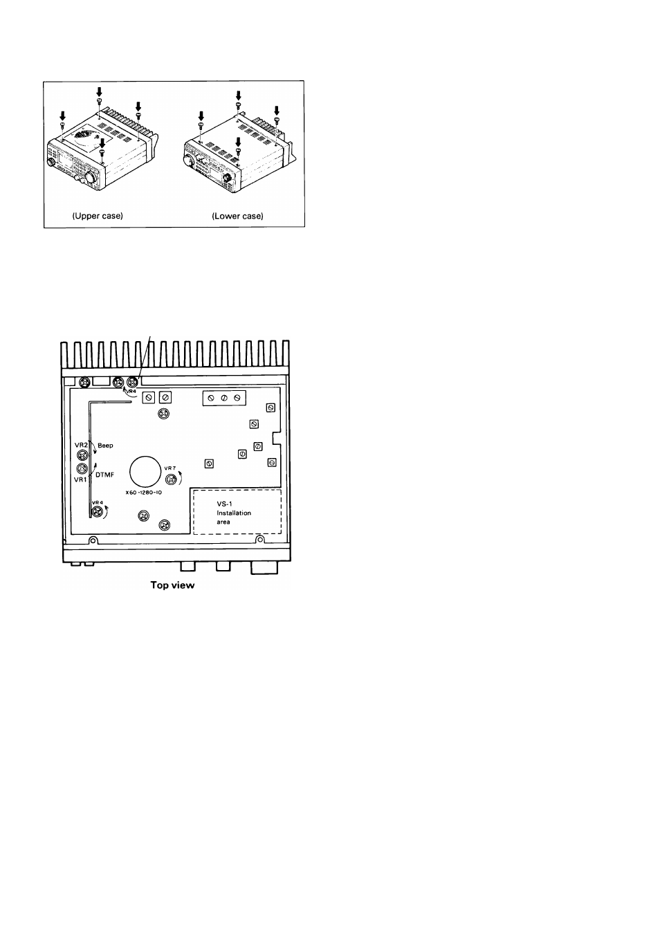
For each of the upper and lower cases, remove four
screws as shown in the illustration. Be careful of the
speaker wiring on the upper case.
Cautions:
1. Before removing the cover, turn the DC power sup
ply's power switch OFF and disconnect the power ca
ble.
2. Do not pinch wiring when opening or closing covers.
Notes:
The following cautions pertain for the adjusting points.
1. Never touch adjustment points other than those indi
cated by the instructions.
2. When adjusting or cutting a part, avoid contact with
nearby parts.
5-6-1. Cover removal
Final unit
5-6-2. Low power output
Adjust VR4 on the Final unit to the desired power level.
Adjustment is possible up to 60W with the TM-2570A,
40W with the TM-2550A/2550E and 20W with the
TM-3530A/2530A.
5-6-3. Microphone gain
VR7 for microphone gain control.
5-6-4. DTMF level
Adjust VR1 (X60-1280-10) to the desired level.
5-6-5. Sidetone and beeper level
The autopatch sidetone level during and beeper level
transmit are adjustable. As the volume is advanced, the
level increases.
1. Adjust the VOL control to your normal listening level.
2. With the PTT pressed any key on the keyboard switch
depressed, adjust VR2.
5-6-6. RF power meter
Adjustment is required after adjusting the low power out
put. VR4 for RF power meter.
34