8-1. dcl system description, 8. dcl (digital channel link) system – Kenwood TM-3530A User Manual
Page 23
Attention! The text in this document has been recognized automatically. To view the original document, you can use the "Original mode".
4-8. DCL (Digital Channel Link) SYSTEM
(The optional modem unit MU-1 is required for DCL sys
tem operation.)
* Packed with a variety of new ideas, the DCL system
makes possible multiple functions with simple opera
tion.
* The DCL system incorporates additional features but is
compatible with the current DCS system.
4-8-1. DCL system description
A. Automatic QSY from any frequency to an open
channel
The DCL system searches, on command, for an open
channel, remembers it, returns to the original frequency
and transmits control information to the receiving station
that switches both radios to the open channel. Micro
processor control assures fast and reliable operation of
the DCL system.
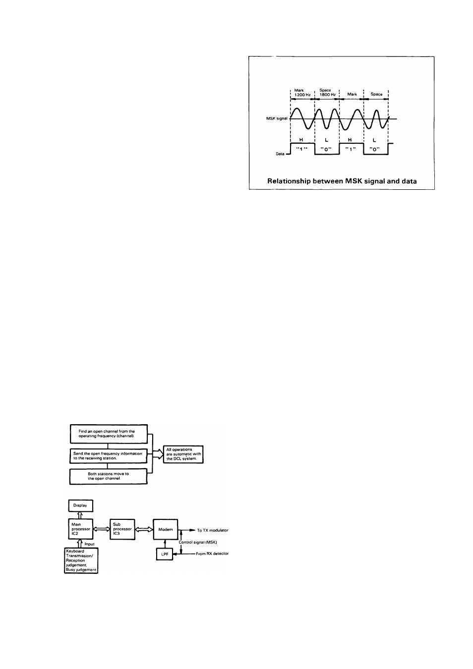
B. Operating principle of DCL system
The circuit concept of the DCL system is shown in the
diagram. IC2 is the main processor which controls the
DCL system's input/output processing and other general
functions. ICS is a processor concerned primarily with
data processing, and Modem (modulator/demodulator) is
the data transmission LSI using MSK (Minimum Shift
Keying). As the digital data interface, the modulator sec
tion sends data required for transmission as a MSK sig
nal synchronized with the clock. The demodulator sec
tion decodes the incomming MSK signal to obtain the
data signal, and also reproduces the clock signal at the
same time. Required data is exchanged between these
ICs as is the clock data, so as to process various func
tions.
Conventional method (manual)
DCL system
Concept of DCL system
C. Digital code memory function for handling
multiple stations, plus standby functions:
There are 100,000 5-digit code groups possible. Several
different codes can be stored in memory.
D. Recall and reverse functions for preventing
received station being lost:
When the DCL system of the station which has received
digital signal is not ON, or when skipping to an open
channel is not possible, due to interference or distur
bance, instructions to the called station can be easily
retransmitted.
E. Automatic transmission and display of call sign
Up to 6 characters can be input as the call sign. Alth
ough the input uses ASCII codes, 2-digit hexadecimal
numbers are actually utilized for call sign entry. Each
code is converted into an ASCII code inside the radio.
Call sign data is transmitted as long as the DCL switch is
ON. An unique feature of this system is that by combin
ing it with the optional CD-I 0 call sign display, it can de
code the signal from a station which uses the DCL sys
tem and display that call sign alphanumerically.
F. New code squelch function with repeater
operation
Code squelch is a selective squelch system operated thru
the use of digital codes. It allows you to listen only for
those stations that transmit the proper digital code. It is
especially powerful when more than one station is on the
frequency, like when using repeaters. Its advantages are;
1 ) Very few operation errors thanks to digital control; 2)
Multiple access code monitoring; 3) Possibility of linkage
to an open channel even during long periods of inactiv
ity. When operating on a repeater, the control signal (as
shown in the diagram) is transmitted to assure proper
code squelch operation.
23