Control signals for chl operation – Kenwood TM-3530A User Manual
Page 24
Attention! The text in this document has been recognized automatically. To view the original document, you can use the "Original mode".
Control signals for CHL operation
Control signal:
^ ; The control signal with channel data
^ : The control signal with no channel data
Beep:
Beep 1
Beep 2
Flashing CHL indicator-
DCL system indicator ON
I
Beep 2
CHL indicator ON
Time
DCLSW
CHLSW
ON
ON
Time
Original RX freq.
Open channel RX
QSY
Fig. a. Simplex mode
Time
DCL system indicator ON
Flashing CHL indicator
Beep 1
CHL indicator ON
^Beep 2_________
ON ON
Sub tone
1
Sub tone ^
Time ——
Original RX f r e q . - 4 — O p e n channel receive
ON
Approx. 1 sec.
PTT SW
OFF
Fig. b. Offset mode (TM-3530A/2570A/2550A/2530A)
DCL system indicator ON --------------------
Beep 1[«^
— Flashing CHL indicator
^
CHL indicator ON^
'*"^Beep 2
Time
DCLSW
ON
CHLSW
ON
Beep 1
1750 Hz
tone
Time
TONE SW TONE SW PTT SW
ON
OFF
ON Approx. 1 sec.
T
Original RX freq..« t t Open channel RX
Fig. c. Offset mode (TM-2550E)
QSY
PTT SW
OFF
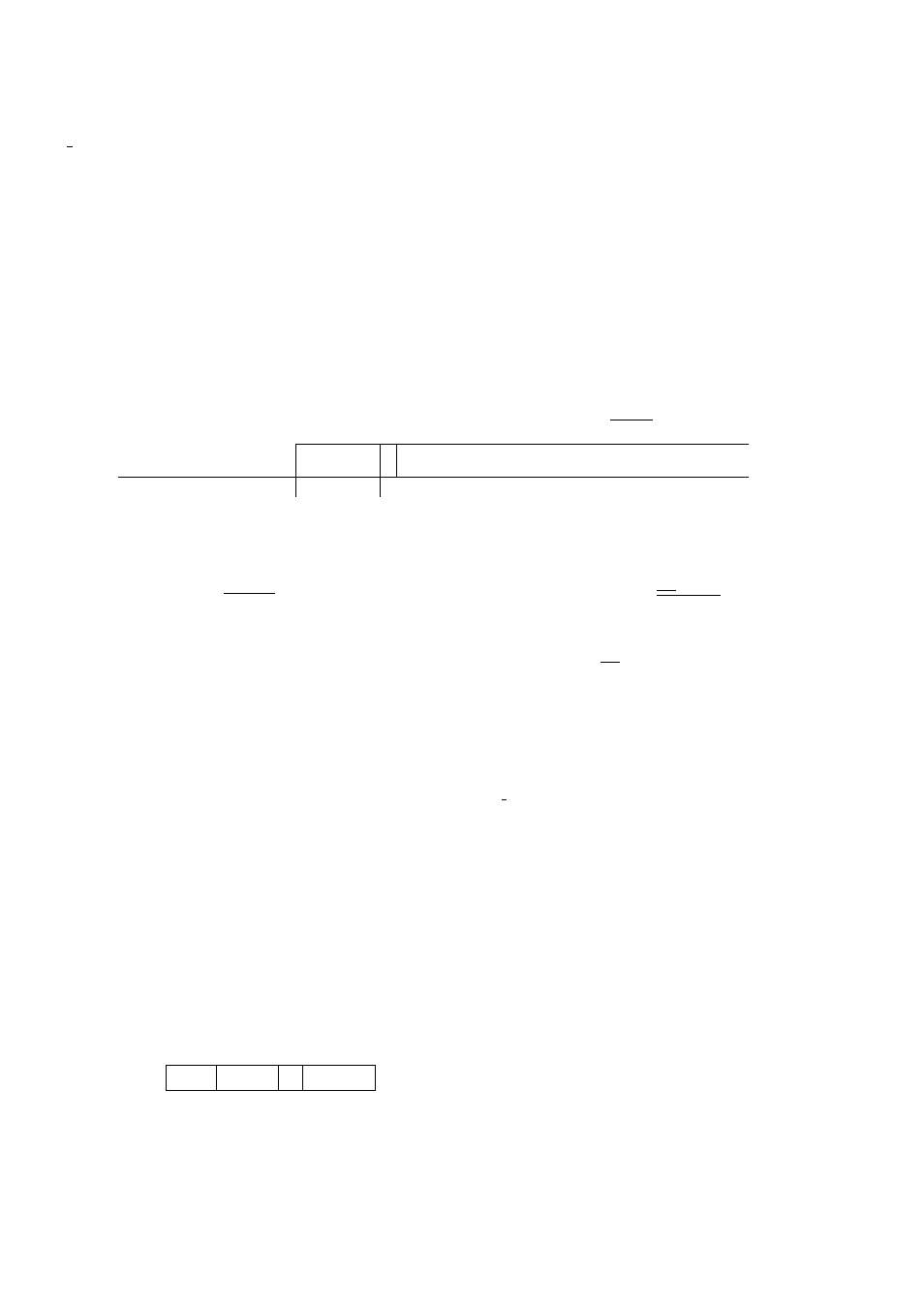
G. Control signal of DCL system
The DCL control signal consists of: 1) Bit/frame sync
signal for distinction of the DCL signal from noise or
other data communication signals; 2) 5-digit digital code
data for station recognition; 3) Open channel data; and 4)
Call sign data which is a combination of alphanumeric
data. Auxiliary data is also provided for future system ex
pansion. This control signal is transmitted at a speed of
1200 baud, requiring approx. 0.2 seconds, which has al
most no effect on normal communication. A beep sound,
peculiar to DCL, (similar to the sound of "packet radio") is
heard when this signal is received.
Synchronizing signal
u------ H—
Oigitat
Channel
Call sign
code
data
data
Composition of control signal
Time
DCL operation control signal
^ The control signal with no channel data
________ DCL system indicator lighting.
t !
DCL SW PTT SW
ON
ON
PTTSW
OFF
Fig. a. Simplex mode
--------------DCL system indicator ON-
DCL SW „
ON
PTT SW
Appro* 1 sec
PTTSW
OFF
Fig. b. Offset mode
(TM-3530A/2570A/2550A/2530A)
___________ DCL system indicator ON_
DCL SW
ON
' Approx 1 sec
PTTSW
ON
PTTSW
OFF
Fig. c. Offset mode (TM-2550E)
24