Carl Goldberg GBGA1064 User Manual
Page 9
9
2.
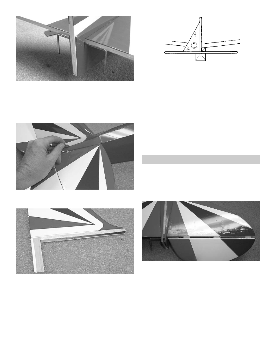
Slide the fin mounting post into the rear of the
fuselage.
Check the fit. The fin should fit easily into the
slot at the rear of the fuselage and the notch
in the rear of the stab. The fin should stand
upright by itself. Enlarge the notch, if neces-
sary.
TAKING CARE NOT TO CUT INTO THE
WOOD STRUCTURE UNDERNEATH, and
working inside the drawn lines, carefully
remove the covering where the fin mounts on
the fuse and stab.
4.
When satisfied with the fit, mark the location
of the fin on the fuse and stab by drawing a
line on both sides of the fin, as shown.
5.
Remount the fin on the fuse and, using a 90º
triangle, make sure the fin is perpendicular to
the stab.
When satisfied with the fit, remove fin and mix
up a couple of spoonfuls of epoxy.
Apply a THIN, even coat of epoxy on the bot-
tom of the fin and along both sides of the fin
mounting posts. Avoid too much glue, which
will squeeze out from underneath the fin.
Mount the fin on the fuse and place the trian-
gle against the fin to make sure it is perpendi-
cular.
Use masking tape to secure the fin and trian-
gle in position until the epoxy is thoroughly
dry. Make sure not to glue the triangle!
ELEVATOR HINGING
1.
Collect the following items:
(1) Rudder
(2) Elevator
(6) Hinges
2.
Take three hinges and, as with the aileron
hinge installation, insert the hinge into the ele-
vator, using straight pins to ensure the hinge
stays centered between the stabilizer and the
elevator.
Inset the elevator joiner wire into the hole and
slot in the elevator, then slide the exposed
side of the hinges into the slots in the stab
until the pins touch both the stab and the ele-
vator.