Carl Goldberg GBGA1064 User Manual
Page 11
11
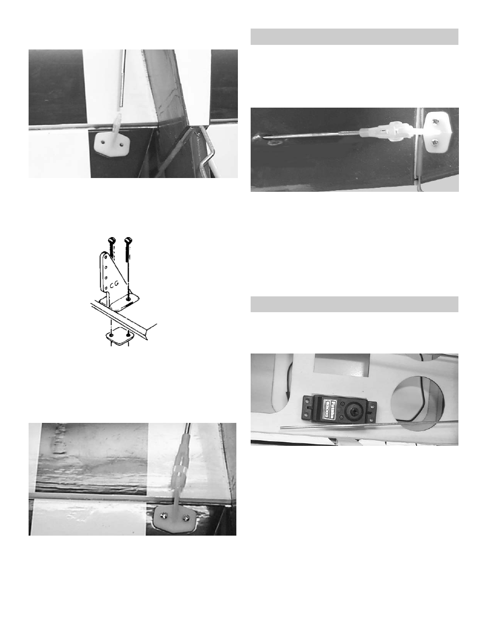
3.
Turn the fuselage over and pull the pushrod
out to the elevator.
Place the control horn so that it is at the end
of the pushrod and the clevis holes are over
the hinge line.
4.
Mark the location of the mounting holes.
Using a 5/64" drill bit, drill the holes through
the elevator.
Using two 2-56 x 3/4" screws, screw the con-
trol horn and the backplate tightly to the eleva-
tor.
5.
Place the silicone keeper over the pushrod.
Thread the nylon clevis onto the pushrod.
Snap the clevis onto the outer hole in the con-
trol horn.
Pull the silicon keeper onto the nylon clevis.
RUDDER PUSHROD
1.
Collect the following items:
(1) Control horn
(2) 2-56 x 3/4" machine screw
(1) .072 x 27-1/4” Threaded Rod
(1) Nylon Clevis
(1) Silicone Clevis keeper
2.
Insert the rudder pushrod just like you did the
elevator.
Place the control horn so that it is at the end
of the pushrod and the clevis holes are over
the hinge line.
Mark the location of the control horn mounting
holes. Try to mount the control horn over the
tailwheel wire so that the mounting screws are
on either side of the wine in the rudder.
ELEVATOR & RUDDER SERVO
1.
Collect the following items:
(1) Fuselage
(2) Servo with hardware (Not Included)
(2) Swivel Keeper
2.
Mount the elevator servo in as shown above.
Tape the elevator and the rudder so that they
are level with the stabilizer and the fin.