Carl Goldberg GBGA1064 User Manual
Page 10
10
3.
Remove the pins in each hinge and, keeping
the elevator/stab assembly in position, apply 3
or 4 drops of thin CA to each hinge, on both
the top and bottom sides of the stab.
Allow ten minutes for the CA to cure before
flexing the elevator. Then install the second
elevator.
RUDDER HINGING
1.
Collect the following items:
(1) Rudder
(1) Tail Wheel Bracket
(3) Hinges
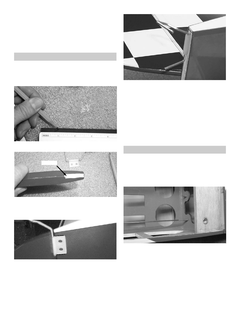
1.
Mark 1” up from the bottom of the rudder.
2.
Drill a 3/32” hole on the hinge line at the 1”
mark you just made.
Cut a slot along the rudder hinge line for the
tailwheel wire to fit into.
Drill Hole
3.
Mark where the tail wheel bracket meets the
fuselage.
4.
Make a slot on the hinge line in the fin post for
the nylon tail wheel hinge bracket.
Place one drop of oil on the nylon hinge where
the wire goes through the hole.
Mix some epoxy for the nylon tail wheel hinge,
the glue the tail wheel hinge into the rudder
post.
Install the hinges into the rudder and glue the
rudder in place using the same hinging
method used for the elevator and
ailerons.Remember to leave a 1/32” gap at
the top of the rudder.
ELEVATOR PUSHROD
1.
Collect the following items:
(1) Control horn
(2) 2-56 x 3/4" machine screw
(1) .072 x 27-1/4” Threaded Rod
(1) Nylon Clevis
(1) Silicone Clevis keeper
2.
Insert one of the .072 x 27-1/4” threaded rods
into the elevator pushrod tube.