Carl Goldberg GBGA1064 User Manual
Page 16
16
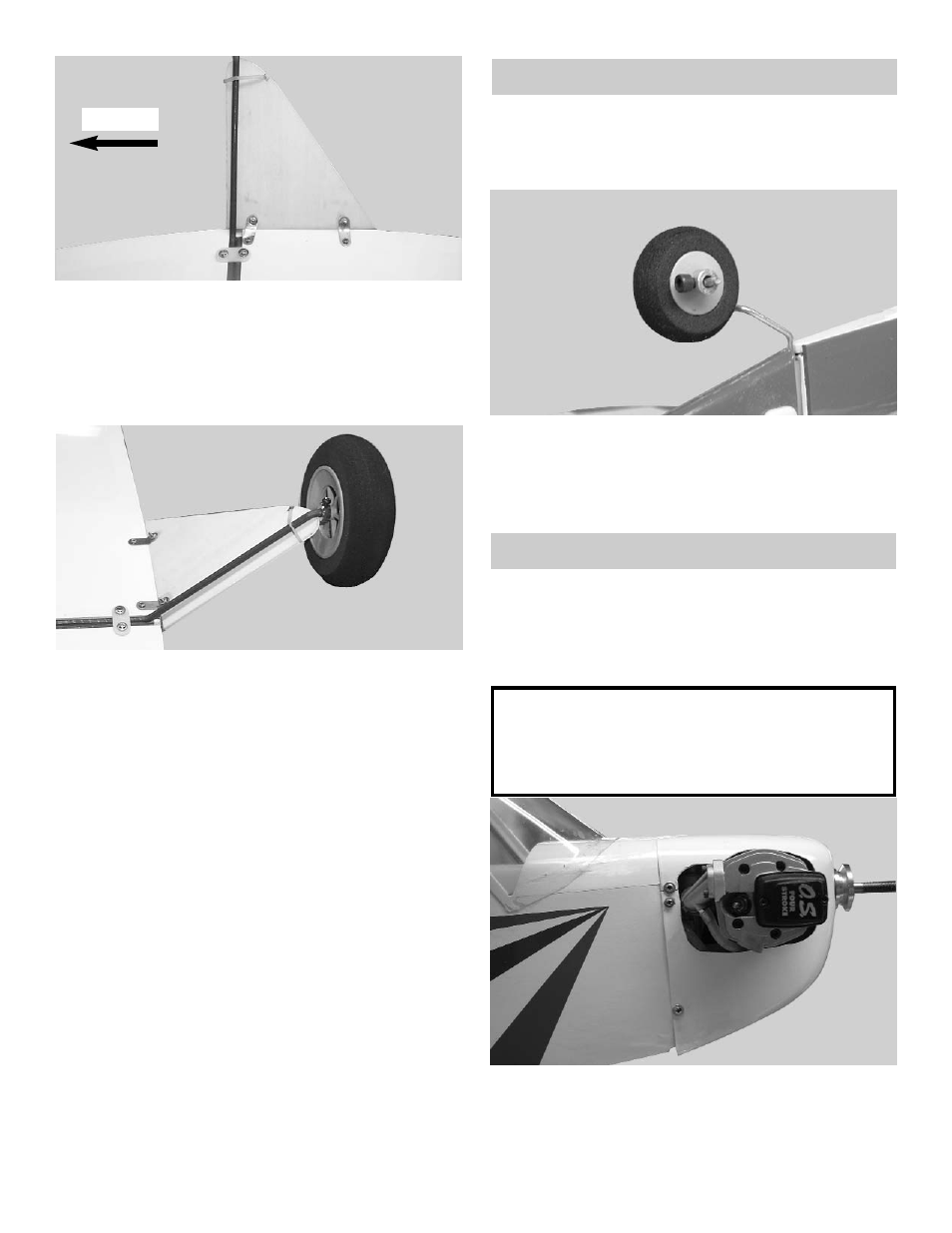
3.
Mount the fairing on the bottom of the plane
as shown above.
Drill a 1/16” hole for the brass straps and
screw them down with the #2 x 3/8 screws.
Place the small rubber band over the landing
gear wire and into the notch on the fairing.
Forward
4.
Place one 5/32 wheel collar on the end of the
axle.
Insert the wheel onto the axle.
Place the second 5/32 wheel collar on the out
side of the wheel.
Center the wheel and the wheel collars on the
axle.
Tighten both the inside and the out side col-
lars.
Repeat for the other side of the landing gear.
TAIL WHEEL
1.
Collect the following items:
(1) 1-1/2” Wheel
(1) 3/32 Wheel Collar with Set Screw
2.
Slide the 1-1/4” wheel onto the tail wheel
bracket.
Place a 3/32” wheel collar on the axle and
tighten the set screw.
COWL INSTALLATION
1.
Collect the following items:
(1) Cowl
(1) Fuselage
(4) #2 x 3/8 Sheet Metal Screw
Note:
Your cowl installation may be differ-
ent then shown depending on the
motor used.
2.
Very carefully start removing the side of the
cowl where the engine will protrude.
Make sure that you leave space around the
engine so that the cowl will not rub on the
engine.