Carl Goldberg GBGA1064 User Manual
Page 12
12
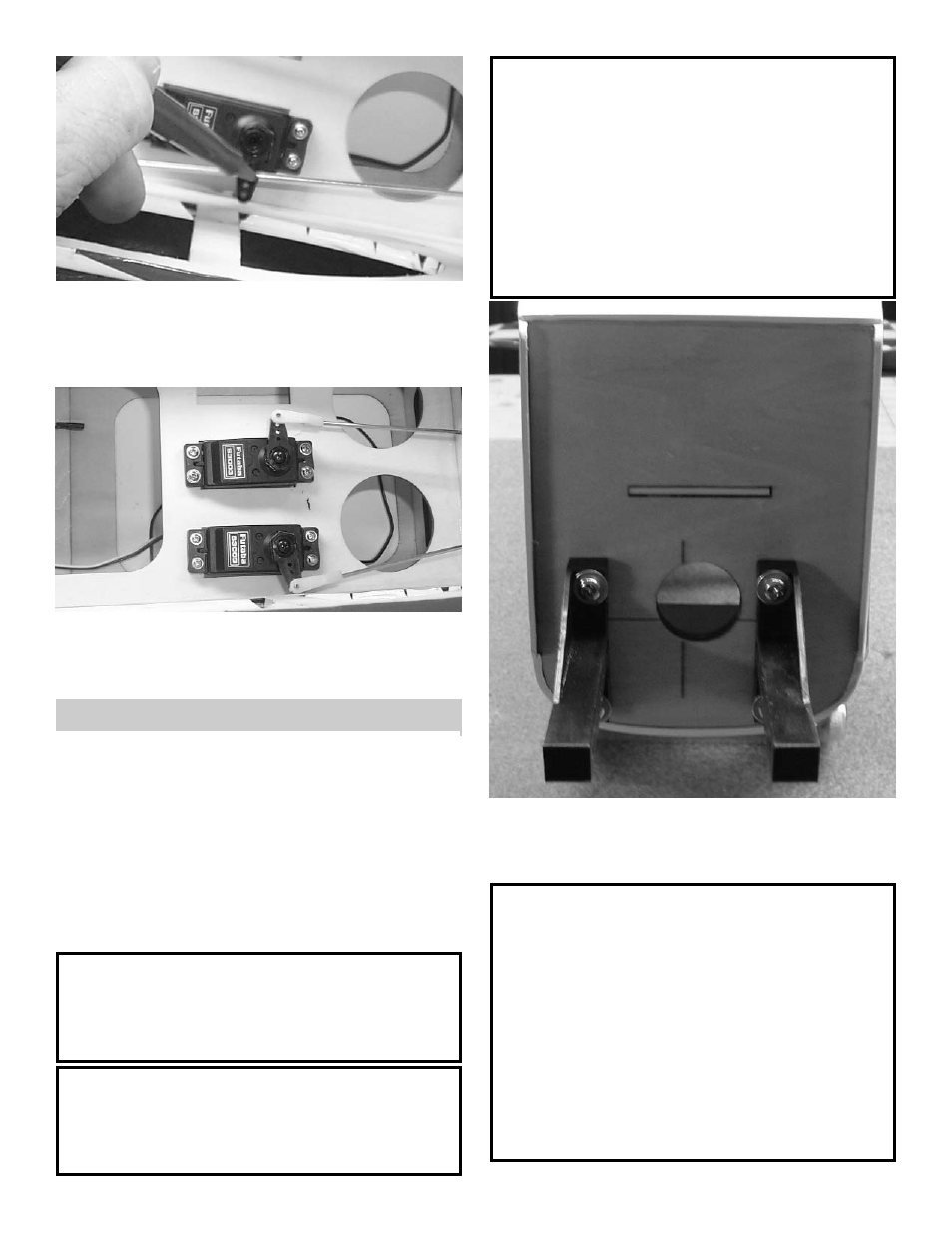
3.
Measure the length of the pushrod to the
servo arm hole and make a 90 degree bend.
Mount the swivel keeper on to the wire and
clip in place.
4.
Repeat steps 2 & 3 for the rudder servo.
The servo should look the same as above
when finished.
INSTALLING THE ENGINE
1.
Collect the following items:
(2) Motor Mounts
(1) Engine
(4) 8-32 x 3/4” Philip Head Screw
(4) 8-32 x 1” Philip Head Screw
(4) #8 Washer
(4) 8-32 Nylon Locking Nut
Note:
Your engine installation may be dif-
ferent then shown depending on the
motor you use.
Caution:
Always use thread lock on any type
of machine bolt and nut.
Note:
This installation is for a inverted
mounted engine. If you wish to have
a side mounted engine, then your
installation steps may be different.
You also might need
a round style motor mount and not
use the one beam mounts supplied in
this kit..
2. Using thread lock, mount the motor mounts to
the firewall using 8-32 x 3/4” screws with #8
washers.
Note:
The firewall is pre-drilled so that the
mounts have an opening of 1.67” this
will fit a O.S. 70 Surpass up to a O.S.
90 Surpass. The motor you choose
might require a different spacing. The
blind nuts can be removed and
changed if required.