Carl Goldberg GBGA1064 User Manual
Page 14
14
6.
Install the throttle servo into the servo tray.
Insert the pushrod wire through the connector
on the servo arm.
mount the servo arm onto the servo.
Note:
Do not cut the remaining pushrod wire till you
align the servo with the radio.
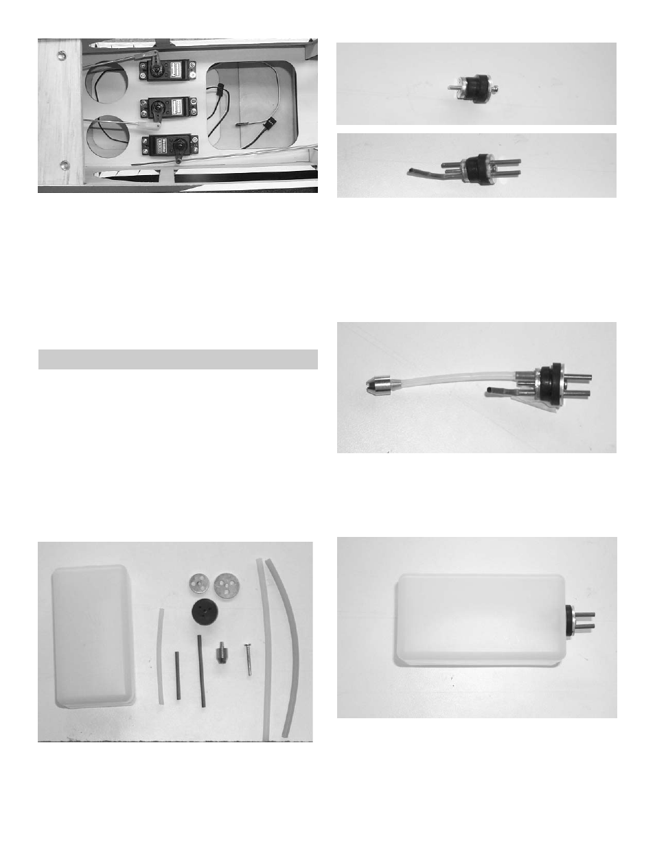
1.
Gather the following items
(1) fuel tank
(1) rubber tank stopper
(1) clunk
(1) 3mm x 25mm screw
(1) cap washer large
(1) cap washer small
(1) 3mm x 40mm brass tube
(1) 3mm x 60mm brass tube
(1) silicone tube 4mm x 80mm
(2) silicone tube 5mm x 165mm
2.
Insert the 3mm screw through the center hole
in the large washer, through the center hole in
the rubber washer against the large side, and
screw the small washer on the back side.
FUEL TANK ASSEMBLY
3.
Insert the brass tubes through two of the
holes. They should be arranged so as the long
one will be on the right side of the plane and
the short one on the left side.
The tubes should extend out the front of the
cap 5/8”. Bend the long tube up at about a 20
degree angle. This should be adjusted so the
end of the tube almost touches the top of the
tank when installed.
4,
Install the 4mm silicone tube to the short
brass tube and install the clunk to the other
end of the silicone tube. This is the fuel pick-
up and must be free to “flop” around in the
tank so it can pick up fuel in any attitude.
5.
Install the assembly into the tank so the vent
tube is turned up to the top of the tank and is
positioned on the right side of the tank.
Tighten the screw to expand the rubber cap.
Don’t over tighten or you could split the tank.