Carl Goldberg GBGA1064 User Manual
Page 8
8
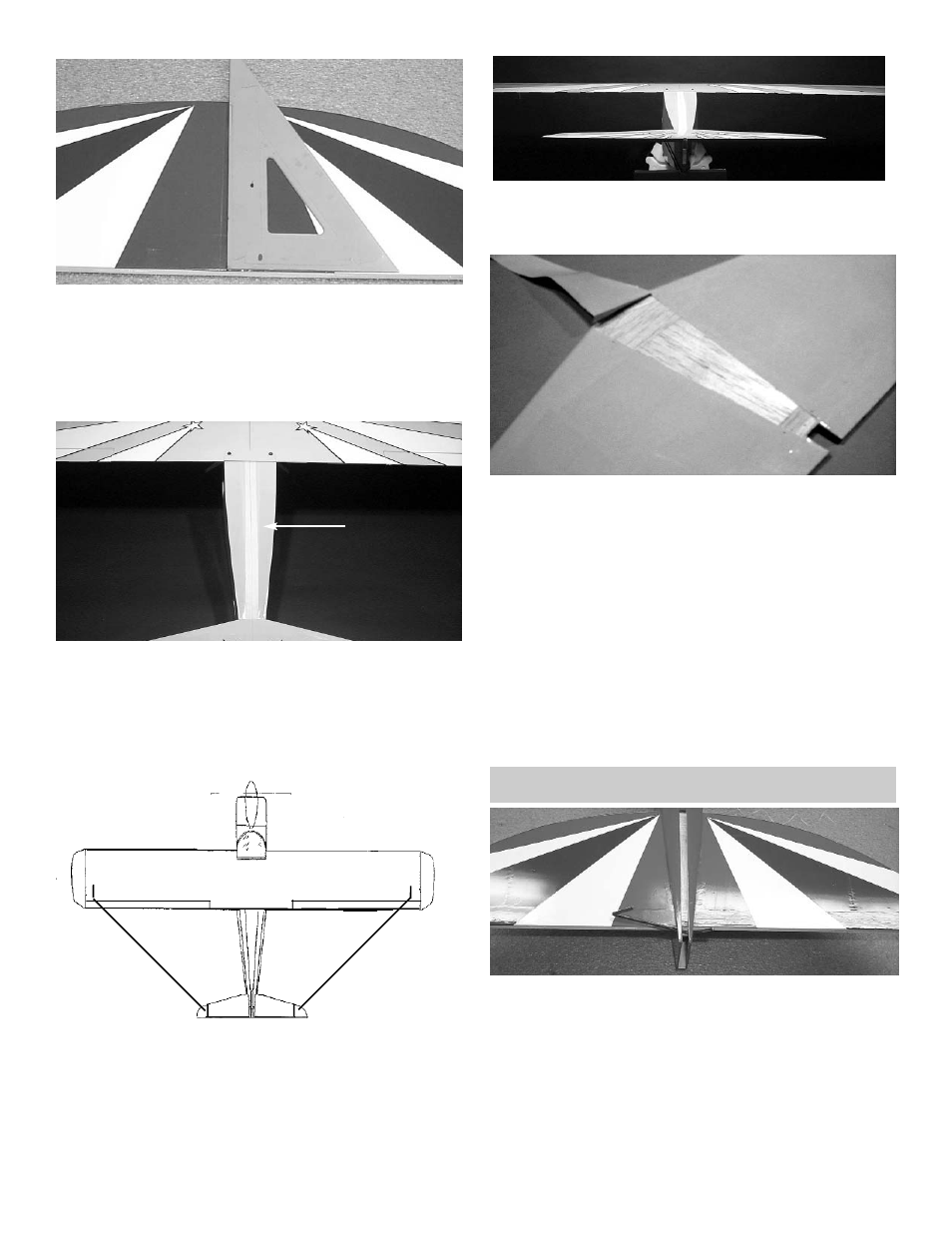
5.
From the center point on the stab, draw a ver-
tical line up to the top of the stab.
Place masking tape on the top of the fuse, just
in front of the stab.
Measure and mark the center point on the
tape.
Mark a centerline on the fuselage, just behind
the wing.
Place a piece of masking tape along the top of
the fuselage, as shown, and draw a line from
the center mark in front of the stab up to the
center mark below the wing.
6.
Place the stab on the platform with the center
of the stab lined up with the center point on
the fuse.
Measuring from the mark on each wing tip to
the mark on the stab tip, make sure the dis-
tance "X" on the right side is the same as the
distance on the left side.
TAPE
x
x
7.
Check to see that the stab is level (parallel)
with the wing. If necessary, insert paper strip
shims to achieve proper alignment.
8.
When satisfied with the alignment of the stab,
temporarily tape it securely in place.
Mark the area on the bottom of the stab where
it rests on the fuse.
Remove the stab from the fuse and, working
1/4" inside the drawn lines, carefully remove
the covering from the bottom of the stab. BE
CAREFUL TO AVOID CUTTING THE WOOD.
9.
Spread epoxy on both the bottom of the stab
and the stab platform of the fuse.
Replace the stab on the platform and, after
again checking the alignment of the stab to
the wing, allow the epoxy to dry thoroughly.
FIN INSTALLATION
1.
Insert the elevator joiner in through the space
behind the stabilizer slot.