Carl Goldberg GBGA1064 User Manual
Page 6
6
AILERON CONTROL HORN INSTALLATION
1.
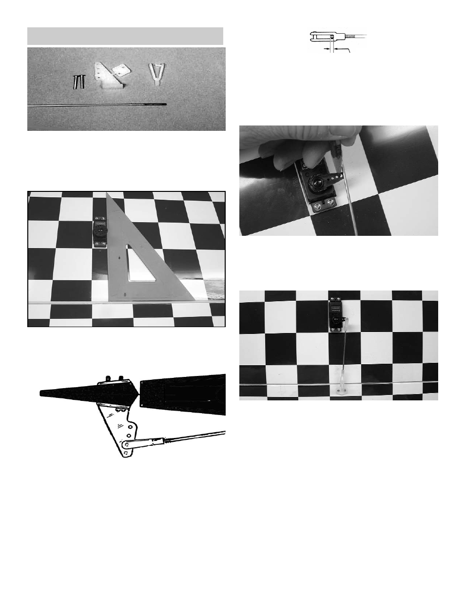
Collect the following items
(2) Large control horn with back plate
(4) 2-56 x 3/4" screw
(2) .072 x 10" threaded wire
(2) Snap link
(1) Nylon Swivel Keeper
2.
With the aileron servo in place, make a mark
at a 90º degree angle to the trailing edge and
in line with the side of the servo.
3.
Position the control horn so that the snap link
holes are on the mark just made and right next
to the hinge line, as shown.
4.
Using a 5/64" drill bit, make a pilot hole in
each screw location.
Mount the control horn with the 2-56 x 3/4"
screws.
5.
Thread the .072 x 10” rod onto the snap link.
Make sure the rod shows in the center of the
snap link.
Place the snap link in the second hole from
the top on the control horn.
6.
Making sure the aileron is in neutral (level)
position, mark where the wire meets the hole
on the servo arm.
Remove the wire and cut it about 1/2" beyond
the mark.
1/16"
Make a 90º bend (or a "z" bend, if preferred)
in the wire and insert the wire in the servo
arm.
Secure the wire with a nylon swivel keeper.
Repeat for the other servo in the other wing.