Carl Goldberg GBGA1064 User Manual
Page 13
13
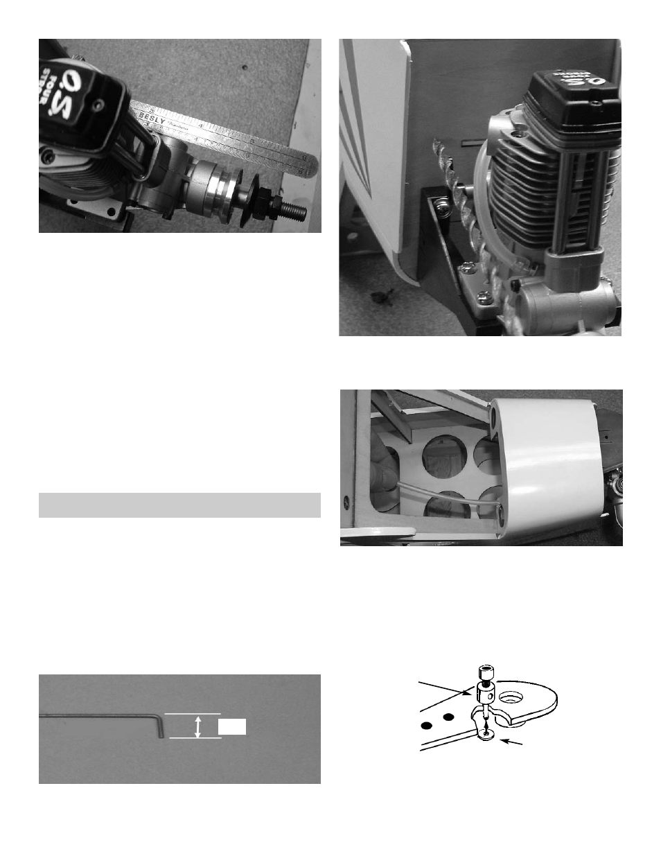
3. Place your motor on the motor mounts,
Center the motor between the mounts.
Measure from the firewall to the prop drive
washer 4-7/8 “.
Mark one of the engine mounting holes loca-
tion.
Using a 3/16 bit, drill on the mark.
Mount the motor to the motor mount using a 8-
32 x1” bolts and the #8 locking nut.
repeat for the other three motor mounting
holes.
1.
Collect the following items:
(1) .072 x 15” threaded wire
(1) 1/8 x 9” nylon guide tubing
(1) Snap nut
(1) Pushrod connector
(1) 4-40 x 1/4” screw
NOTE: The following photos and instructions are for
mounting a 4-cycle engine. Other engines
might require different steps for installations.
THROTTLE PUSHROD INSTALLATION
2.
Mark 1/4” from the end of the .072 wire and
make a 90º bend.
1/4”
3. Drill a 1/8” hole in the firewall in position with
the throttle arm.
Insert the 1/8” x 9” nylon tubing in the hole.
4. Let the tubing exit into the fuselage towards
the throttle servo mount.
Insert the throttle pushrod thru the tubing
starting at the firewall.
Insert the bent end into the throttle arm on the
carburetor.
PUSHROD CONNECTOR
SNAP NUT
5.
Attach the Pushrod connector to a servo arm
same as shown above.