Carl Goldberg GBGA1064 User Manual
Page 20
20
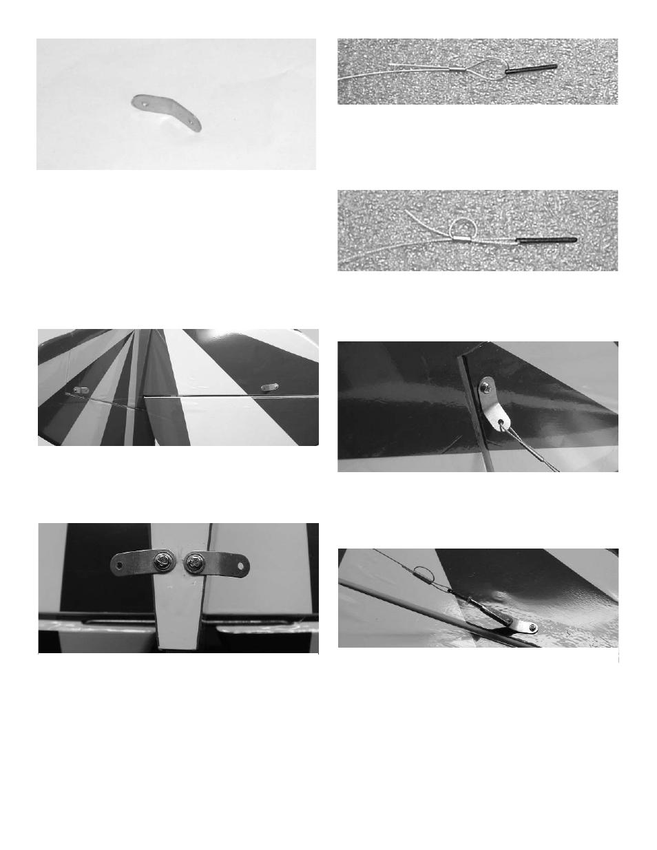
2.
Take the 8 flat brackets and bend in the
middle to about a 30 degree angle.
Use the three 2-56 x 1/2” screws with a wash-
er under the head, and mount the brackets to
the fin and stab with the aircraft nut on the bot-
tom.
Caution:
Use thread lock on all bolts and nuts.
3.
The brackets go on each side of the fin and
stab with one bolt holding two on. There is a
predrilled hole at each location. Hold up to a
light to help locate the hole under the cover-
ing.
4.
Measure forward 1” from the rudder hinge
line.
Mount the other two brackets with the one
larger hole to the bottom of the fuselage using
the #2x1/2” sheet metal screws.
6.
Loop the end of the cable back though the
brass tube.
Use pliers and crimp the brass tubing onto the
cable to secure it.
5.
Insert the cable through the 1/16 OD x 1/4”
brass tubing.
Next thread the cable though the hole at the
end of the 2-56 threaded rods and pass it
back through the brass tube.
7.
Screw a golden clevis on the rigging coupler.
and attach it to the bracket at the fin.
Pull the cable to the bracket on the stab and
cut 2” past the hole.
8.
Pass the cable through the brass tube,
through the bracket on the stab and back
through the brass tube.
Pull the cable tight, but be careful not to put
pressure on the stab or fin. we want the cable
to just be snug at this point and we will adjust
the tension after all four are in place.
Loop the cable back through the brass tube
again and crimp.
Use pliers and crimp the brass tubing onto the
cable to secure it.