Figure 6.18, Propane air regulator measuring taps, Maintenance – AERCO KC1000 Heater w/Mod-Box Controller User Manual
Page 41
MAINTENANCE
36
122537). The use of Permatex or a similar
gasket adhesive is recommended.
26. Replace the gasket between the manifold
and tubesheet (P/N GP-18900). Do not use
any gasket adhesive; this gasket has an
adhesive backing
27. Beginning with the manifold, reinstall all the
components in the reverse order that they
were removed.
6.8.1 PROPANE UNITS
For propane units it will be necessary to remove
the air mix assembly in addition to the steps
outlined in Section 6.8. Proceed as follows:
1. Follow steps 1 through 5 under Section 6.8
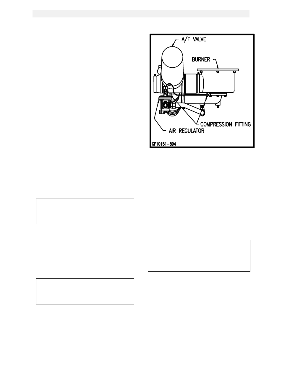
2. Using a wrench, loosen the two
compression fittings holding the 1/4”
feedback tube between the burner and air
regulator and remove the feedback tube.
(See Fig. 6.18)
3. Using a 1-1/16” wrench or an adjustable
wrench loosen and remove the 12” flexible
gas hose.
4. Proceed back to Section 6.8 and continue at
Step #6.
NOTE:
Older propane units have a 1/8” Feedback
Tube and 1/8” OD tube compression
fittings.
6.9 HEAT EXCHANGER INSPECTION
The water-side of the heating surfaces may be
inspected by removal of the top heater head.
(See Fig.’s 6.19 & 6.20) The following gaskets
will be needed prior to performing the inspection:
GP-18856
Release Gasket
GP-18532
Shell Gasket
NOTE:
This manual covers two different style
heater heads. The newer is a flat head,
the older is a concave head.
Figure 6.18
Propane Air Regulator Measuring Taps
6.9.1 FLAT (NEW) STYLE HEAD
To inspect the heat exchanger watersides:
1. Disconnect the electrical power to the unit.
2. Close the water inlet, outlet, and
recirculation shut-off valves to the unit.
3. Open the drain valve carefully while opening
the relief valve on the right side of the unit
shell to relieve pressure and allow air into
the shell.
CAUTION!
Do not drain the unit without venting the
shell! A vacuum in the unit may displace the
liner causing serious damage not covered
by warranty.
4. Remove the wing nut from the top center of
the shell cap and remove the cap.
5. Remove the nuts and studs from the upper
head. Remove the upper head and upper
head-liner, (See Fig. 6.19).
6. Inspect and clean the heat exchanger tubes
of scale and all gasket surfaces thoroughly
before reassembling the upper head.
AERCO recommends that NEW gaskets be
used when reassembling.