Maintenance – AERCO KC1000 Heater w/Mod-Box Controller User Manual
Page 34
MAINTENANCE
29
SECTION 6 – MAINTENANCE
6.1 MAINTENANCE SCHEDULE
The KC1000 requires regular routine
maintenance to keep up efficiency and
reliability. For best operation and life of the unit,
the following routine maintenance procedures
must be performed in the specified time-
periods.
WARNING!
TO AVOID PERSONAL INJURY, BEFORE
SERVICING:
(A) DISCONNECT AC POWERTO THE
UNIT
(B) SHUT OFF THE GAS SUPPLY TO THE
UNIT
(C) ALLOW THE UNIT TO COOL TO A
SAFE TEMPERATURE
6.2 SPARK IGNITOR
The spark ignitor assembly is located in the body
of the burner (see Fig. 6.1). The ignitor may be
HOT. Care should be exercised. It is easier to
remove the ignitor from the unit after the unit has
cooled to room temperature.
CAUTION!
The ignitor must be removed and installed
using the ignitor removal tool provided with
the unit(s). Damage to the burner due to
using a socket for removal and installation
of the ignitor is not covered under warranty
To inspect/replace the Ignitor
1. Put the green ON/OFF button on the control
panel, to the OFF position and disconnect
AC power to the unit. Disconnect the plastic
tubing from the condensate cup to drain and
remove the rear cover panels from the unit.
Access to the spark ignitor may also be
gained by removing the unit’s right side
panel
2. Disconnect the ignitor cable from the ignitor
contactor and unscrew the ignitor contactor
from the burner shell.
3. Insert the ignitor removal tool into the burner
shell, where the ignitor contactor was
removed. Screw the outer barrel of the tool
into the burner shell. Push the inner barrel
up and fit the hexagonal end of the tool over
the ignitor. Unscrew the ignitor from the
burner head and then the tool from the
burner shell.
4. The ignitor is gapped at 1/8-inch. If there is
substantial erosion of the spark gap or
ground electrode, the ignitor should be
replaced. If carbon build-up is present, clean
the ignitor using fine emery cloth. Repeated
carbon build-up on the ignitor is an indication
that a check of the combustion settings is
required, (see Sections 4.2 and 4.3 for
Combustion Calibration)
.
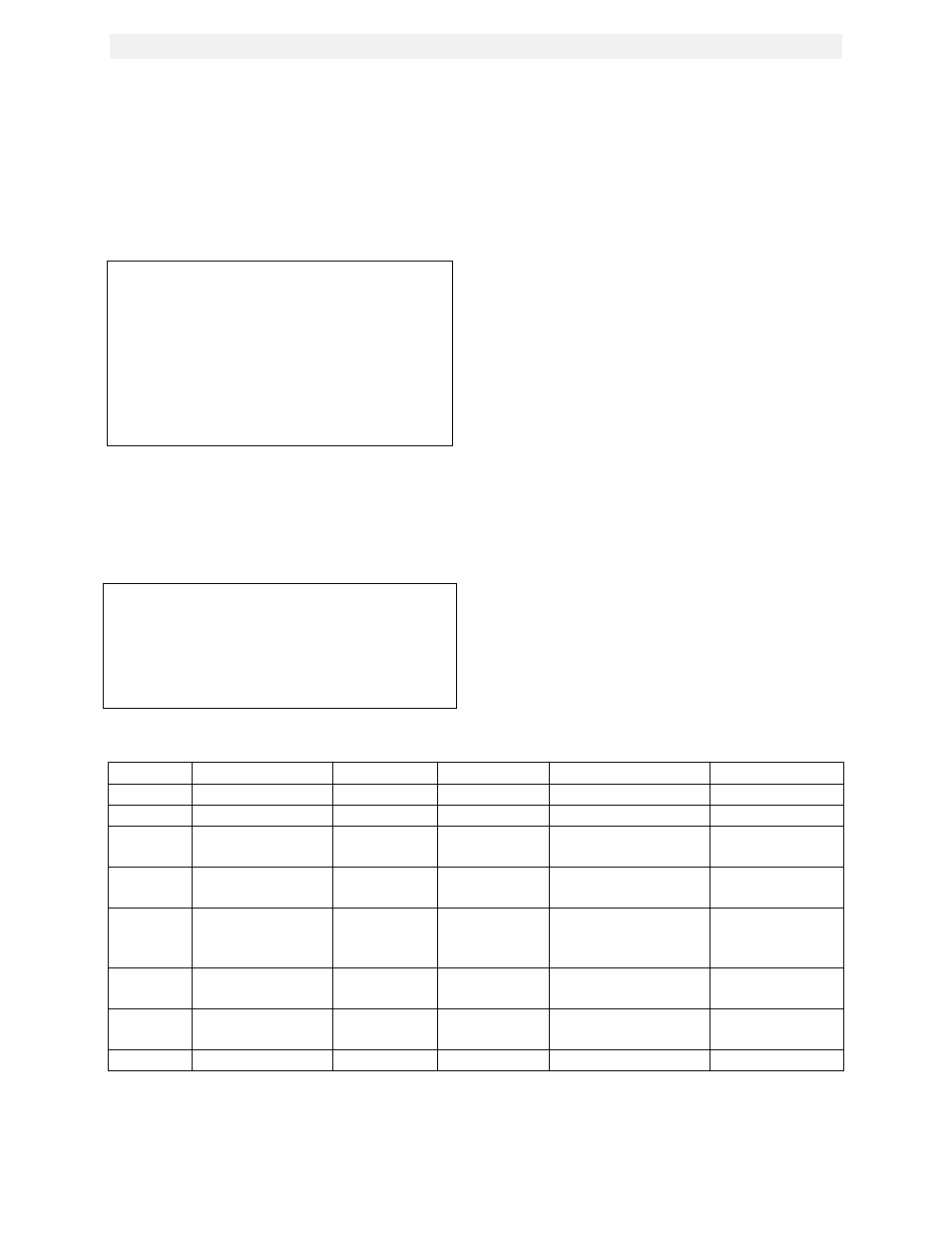
Table 1 Maintenance Schedule
Section
Item
6 Mos.
12 Mos.
24 Mos.
Labor Time
6.2
SparkIgnitor
Inspect
Replace
15 mins.
6.3
Flame Detector
Inspect
Replace
15 mins.
6.4
Combustion
Adjustments.
Check
Check
1 hr.
6.5
Testing of
Safety Controls
Test
20 mins.
6.6
BTU
Transmittert.
Pump
Oil
15 mins.
6.7
BTU
Transmitter
Inspect & clean if
necessary
50 mins.
6.8
*Manifold &
Tubes
Inspect & clean if
necessary
4 hrs.
6.9
Heat Exchanger
Inspect
1.5 hrs.
* Recommended only when unit will be run in an extreme condensing mode for prolonged
periods of time.