Control panel operating procedures – AERCO KC1000 Heater w/Mod-Box Controller User Manual
Page 18
CONTROL PANEL OPERATING PROCEDURES
13
LCD display on the front of the control panel.
They are labeled CLEAR,
!
,
"
, and AUX.
The MAIN display is used during normal operation
of the unit. In the MAIN display, start sequence
and fault messages can be viewed. To return to
the MAIN display from any other display,
simultaneously press CLEAR and the
!
arrow
key. To reset the MAIN display after a fault has
occurred press the CLEAR button.
The CYCLES display indicates the date and time,
and the number of cycles the unit has started.
When in the CYCLES display only the number of
cycles can be reset. To reset the number of cycles
to zero, simultaneously press the
!
"
arrow
keys and hold them for approximately four
seconds.
In the SET DATE display, both the time and date
are displayed and can be changed.
To access the SET DATE display, press the
CLEAR button while in the CYCLES display.
Continue pressing the CLEAR button to move
through the SET DATE display fields. Use the
!
"
arrow keys to set the date and time.
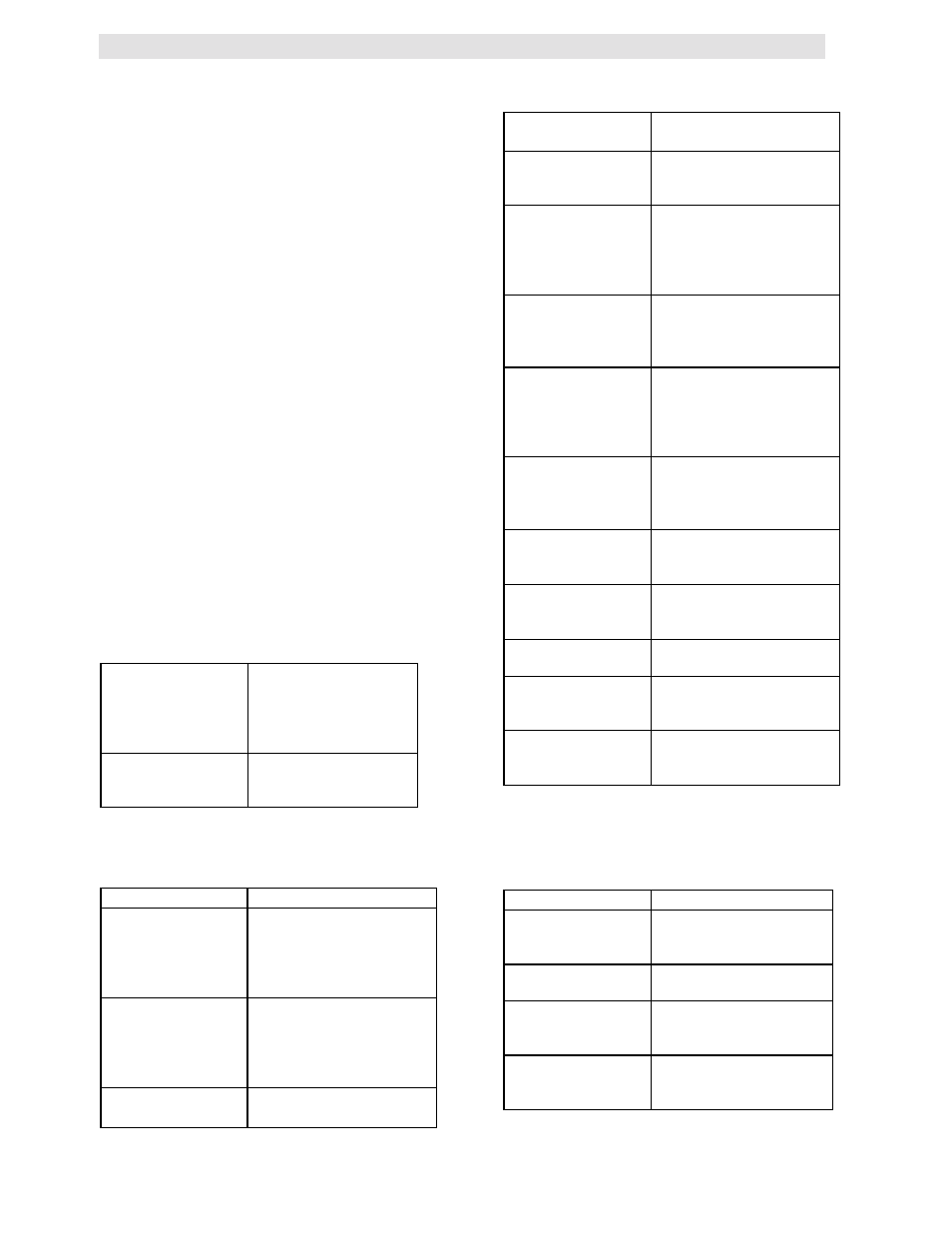
The following table shows the messages
displayed after accessing the CYCLES and SET
DATE DISPLAYS.
# CYCLES =
“DATE” “TIME”
The number of times
the controller has
completed it’s start
cycle, and the time
and date
SET DATE:
“DATE” “TIME”
Displays and allows
setting of the date
and time
3.5.2 ANNUNCIATOR FAULT MESSAGES
The following table lists the Annunciator fault
messages and their meanings.
MESSAGE
MEANING
RESET MAIN
POWER
AC power has been
interrupted. Power must
be shut off for 20
seconds to reset the
display.
HIGH WATER
TEMP
Outlet water
temperature has
exceeded the high
temperature limit
setting.
LOW GAS
PRESSURE
The unit has tripped due
to low gas pressure.
LOW WATER
LEVEL
The unit water level is
below the probe level.
REMOTE
DISABLED
The interlock terminals,
in the relay box, are not
closed.
PURGE INTLK
OPEN
The proof of closure
switch or the purge
switch did not prove
closed during the start
sequence.
LOW AIR FLOW
The air flow switch did
not proved closed
during the start
sequence.
SYSTEM FAULT
PURGE
INTERLOCKS
The proof of closure
switch or purge switch
did not proved closed 45
seconds after the unit
attempted to start.
SYSTEM FAULT
LOW AIR
PRESSURE
The air pressure switch
did not prove closed 45
seconds after the unit
attempted to start.
FLAME FAULT
DURING
IGNITION TRIAL
Flame did not prove at
the end of the trial for
ignition period.
LOCKOUT RUN
AIR FLOW
The air pressure switch
opened after flame was
proven.
LOCKOUT RUN
FLAME
Flame signal was lost
after flame was proven.
LOCKOUT RUN
The combustion
safeguard is locked out.
HI EXHAUST
TEMP
The exhaust gas
temperature has
exceeded 500º F
3.5.3 ANNUNCIATOR START SEQUENCE
MESSAGES
The following table lists the annunciator start
sequence messages.
MESSAGE
MEANING
STANDBY
The unit is in standby
mode waiting for a call
for heat
PURGING
The unit is in the 7 sec
purge.
IGNITION TRIAL
The unit is in ignition
position attempting to
light the burner
FLAME PROVEN
The unit has
established flame and
is running normally.