Figure 3.1, Front panel controls location, Control panel operating procedures – AERCO KC1000 Heater w/Mod-Box Controller User Manual
Page 14
CONTROL PANEL OPERATING PROCEDURES
9
SECTION 3- CONTROL PANEL OPERATING PROCEDURES
The following is a guide to the operation of the
unit’s control panel. Initial startup of this unit must
be performed by factory trained startup personnel.
Operation prior to initial startup by factory trained
personnel will void the warranty.
CAUTION:
All initial installation procedures must be
satisfied before attempting to start the unit
.
WARNING:
DO NOT ATTEMPT TO DRY FIRE THE KC
1000. STARTING THE UNIT WITHOUT A
FULL WATER LEVEL CAN SERIOUSLY
DAMAGE THE UNIT AND MAY RESULT IN
PERSONNEL INJURY OR PROPERTY
DAMAGE. THIS SITUATION WILL VOID
ANY WARRANTY.
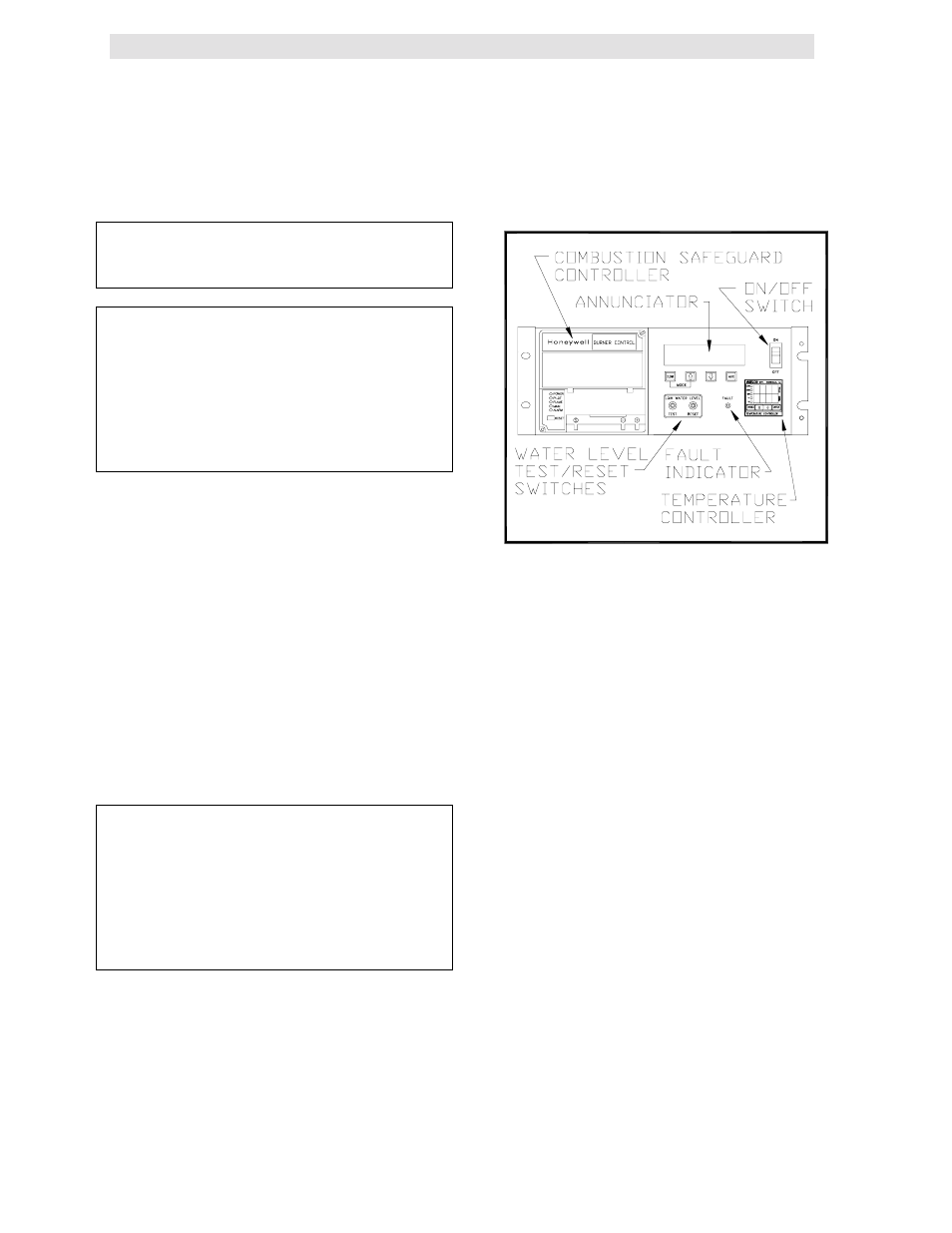
3.1 THE CONTROL PANEL
The KC 1000 Control Panel has been designed to
provide the operator with all the necessary
information required for operation and
troubleshooting the unit. There are six separate
accessible controls or displays, available to the
operator (see Figure 3.1). These are:
1. The Temperature Controller
2. The Annunciator & Function Switches
3. The Combustion Safeguard Controller
4. Water Level Test and Reset Switches
5. On/Off
Switch
6. Fault Indicator Light
The following sections will describe the above
components in more detail.
WARNING
CONTROL BOX INTERNALS MUST NOT
BE SERVICED OR ACCESSED BY OTHER
THAN FACTORY CERTIFIED SERVICE
TECHNICIANS. ALL CONTROL BOX
INTERNALS HAVE THE CAPABILITY OF
HOLDING AN ELECTRICAL VOLTAGE OF
120 VOLTS AC.
3.2 THE TEMPERATURE CONTROLLER
The temperature controller is a PID
programmable controller that utilizes feed forward
and feedback information to accurately maintain a
desired set point. It is the primary source for
programming and viewing operating parameter
settings. It also plays a part in the start sequence
and includes other features such as:
•
2- eight segment LED displays
•
5 indicator status lights
•
3 menu levels
•
RS-485 communications capability,
FIGURE 3.1
Front Panel Controls Location
3.2.1 LED DISPLAYS
The upper and lower displays each consist of four
8 segment LED’s’ (see figure 3.2). When an
operating parameter is chosen to be changed or
looked at, the lower led display indicates the
parameter being looked at in the form of a code.
The upper display indicates the parameter’s value.
For a complete listing of the operating parameters
see Appendix A of this manual.
3.2.2 INDICATOR STATUS LIGHTS
The first LED indicator light, “MAN”) indicates
whether the controller is in auto or manual mode,
(see Fig. 3.2). When lit the controller is in manual
mode and the operator is responsible for
operation of the unit. When the LED is not lit the
controller is in auto mode. In auto mode the
controller is operating the unit from signals
generated by sensors located on the unit.
The second LED, “REM”, designates whether the
controller is being controlled locally or remotely.
(see Fig. 3.1). When lit the controller is in remote
mode and can accept commands from an
external source via the RS-485 interface. When
this LED is not lit the controller is in local mode
and will respond to whatever the current internal
settings are. All external commands are ignored.