Figure 3.14, Figure 3.15, Flame test jack location – AERCO KC1000 Heater w/Mod-Box Controller User Manual
Page 21: Control panel operating procedures
CONTROL PANEL OPERATING PROCEDURES
16
from the ignition transformer and the MAIN
LED lights of the combustion safeguard.
At this point, the annunciator will display FLAME
PROVEN. The unit, in the automatic mode, is
released to modulate through the PID controls.
3.10 AFTER FLAME
Once the control signal has gone below the stop
level (see section 3.12 for Stop Level explanation),
the temperature controller’s green ON light
extinguishes, indicating there is no longer a call for
heat. This signals the combustion safeguard to
shut down the burner. The POWER LED of the
combustion safeguard remains illuminated and the
annunciator displays the message STANDBY.
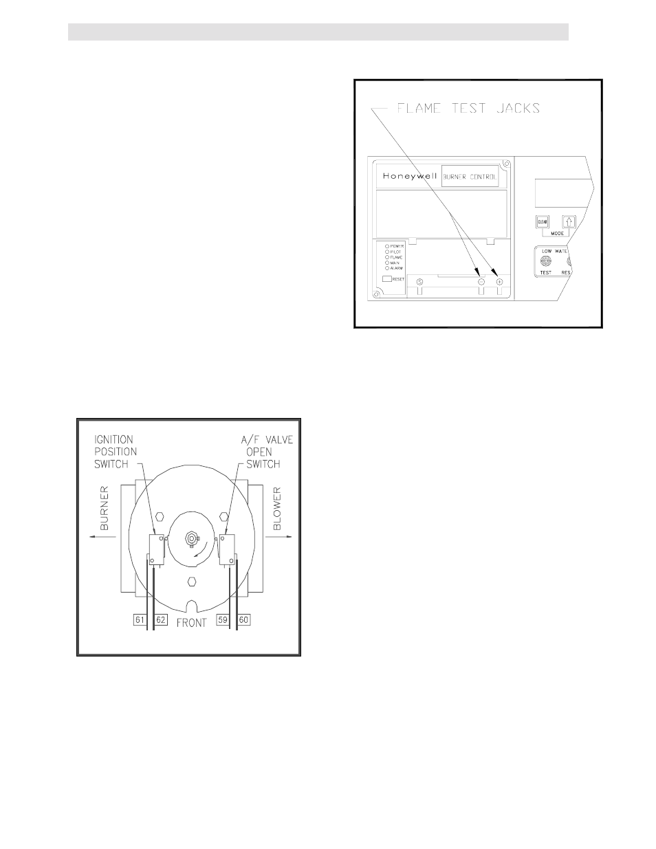
3.11 FLAME TEST JACKS
The front of the combustion safeguard has two
test jacks marked + and - for flame monitoring,
(see Fig. 3.15). To access the test jacks remove
the combustion safeguard cover by turning the
center screw counterclockwise. A standard
voltmeter is required to monitor the flame signal
strength. A flame signal of 1.5 to 5VDC is typical
during proper operation of the unit.
Figure 3.14
Air/Fuel Valve in Ignition Position, Engaging
the Ignition Microswitch
Figure 3.15
Flame Test Jack Location
3.12 START STOP LEVELS
The start and stop levels are the firing rate
percentages that represent a call for heat and an
indication that the call for heat has been satisfied.
The start level is preset to 20% and the stop level
is preset to 16%. These are factory preset and
should not require adjustment.