Figure 5.4, Blower proof switch location and wiring, Figure 5.5 – AERCO KC1000 Heater w/Mod-Box Controller User Manual
Page 32: Ssov actuator set screw location, Figure 5.6, Air/fuel valve cover screw locations, Safety device testing
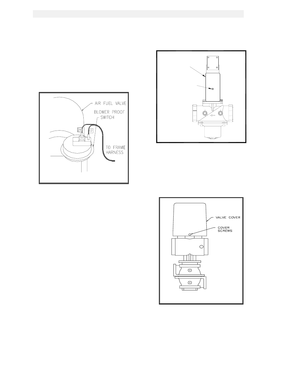
SAFETY DEVICE TESTING
27
2. Disconnect wire #17 from the air pressure
switch located on the air/fuel valve (See Fig.
5.4).
3. Restore AC power to the unit.
4. Produce a “call for heat” to start the unit.
The unit should fault and display the
message SYSTEM FAULT AIR FLOW
SWITCH.
Figure 5.4
Blower Proof Switch Location and Wiring
5. Disconnect AC power from the unit.
6. Replace wire #17
7. Restore AC power to the unit.
8. Reset the combustion safeguard and clear
the annunciator display.
5.7 PURGE INTERLOCKS FAULT TEST
1. Turn the ON/OFF switch to the OFF
position.
2. Loosen the two set screws that attach the
safety shut off valve actuator to its valve
body. (See Fig. 5.5).
3. Lift the SSOV Actuator clear of the valve
body. This will open the proof of closure
switch.
4. Start the unit in manual mode
5. The unit should shutdown and display the
message SYSTEM FAULT PURGE
INTERLOCKS.
6. Clear the annunciator. Turn the ON/OFF
switch to the OFF position.
SSOV ACTUATOR
COVER
COVER SCREW
SSOV ACTUATOR
Figure 5.5
SSOV Actuator Set Screw Location
5. Disconnect AC power to the unit.
6. Remove the air/fuel valve cover by loosening
the 3 screws securing it in place. (See Fig.
5.6).
Figure 5.6
Air/Fuel Valve Cover Screw Locations
9. Disconnect wire #60 from the air/fuel valve
open position switch. This is the switch
closest to the blower (See Fig. 5.7).