Figure 3.11, Proof of closure switch location, Figure 3.12 – AERCO KC1000 Heater w/Mod-Box Controller User Manual
Page 20: Figure 3.13, Blower proof switch location, Control panel operating procedures
CONTROL PANEL OPERATING PROCEDURES
15
3.9 START SEQUENCE
When the unit is in the standby mode, and there
is a demand for hot water, the following will occur:
1. Upon demand the temperature controller’s ON
status indicator will light.
2. The combustion safeguard’s PILOT LED
lights, and the blower contactor energizes,
starting the blower.
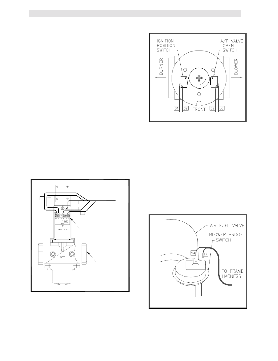
3. The system next checks for proof of closure
from the safety shut-off valve, (see Fig. 3.11),
and the air fuel valve rotates open engaging
the air /fuel valve open switch (see Fig. 3.12).
4. The LCD display shows PURGE INTLK OPEN
until the above conditions are met. Once met
the LCD display will show LOW AIR FLOW.
5. The blower proof switch closes, (See Fig.
3.13), and the LCD display will show
PURGING.
6. Closure of the blower proof switch signals the
combustion safeguard to begin its 7-second
purge cycle.
CONNECTOR
149
VALVE
SHUT-OFF
SAFETY
SWITCH
CLOSURE
PROOF OF
9A
148
145
146
147
FROM
Figure 3.11
Proof of Closure Switch Location
Figure 3.12
Air/Fuel Valve Open and Engaging the
Air/Fuel Valve Open Microswitch
7. At the end of the purge cycle the combustion
safeguard initiates a 10 second trial for ignition
and the following simultaneously occurs:
•
The LCD displays the message IGNITION
TRIAL.
•
The ignition transformer energizes.
•
The air/fuel valve rotates to its low fire
position. This engages the air-fuel valve
closed switch, energizing the safety shut-off
valve, (see Fig. 3.14).
Figure 3.13
Blower Proof Switch Location
8. Once the combustion safeguard detects
flame, its flame LED lights. Power is removed