Auto/manual display with auto on, Figure 3.7, Auto/manual display with manual on – AERCO KC1000 Heater w/Mod-Box Controller User Manual
Page 17: Figure 3.8, Annunciator function switches and lcd display, Control panel operating procedures
CONTROL PANEL OPERATING PROCEDURES
12
Figure 3.7
Auto/Manual Display with Manual ON
3.4 SECONDARY MENU
The secondary menu is primarily related to
temperature control. It is necessary to access this
menu when temperature calibrating the unit.
To access the secondary menu, press the
!
arrow key and ENTER simultaneously. To scroll
through the menu press the INDEX button. The
secondary menu allows access to the following
temperature control features:
Func
Unit’s mode of
operation
tout
Outlet water
temperature
FFt
Water temperature
at the BTU
transmitter sensor
Pct
Firing rate of the unit
in percent
SetP
The desired set point
of outlet water temp
SEnS
High flow
temperature
adjustment
OFSt
Low flow
temperature
adjustment
LLt
Low temperature
alarm
HLt
High temperature
alarm
Pb1
Proportional Band
Int
Integral Rate
Drt
Derivative Time
Fdb
Feedback on or off
Addr
Controller address
for external
communication
LOre
Local/ remote status
of the control
For a complete explanation of the secondary
menu parameters see the Appendix A of this
manual.
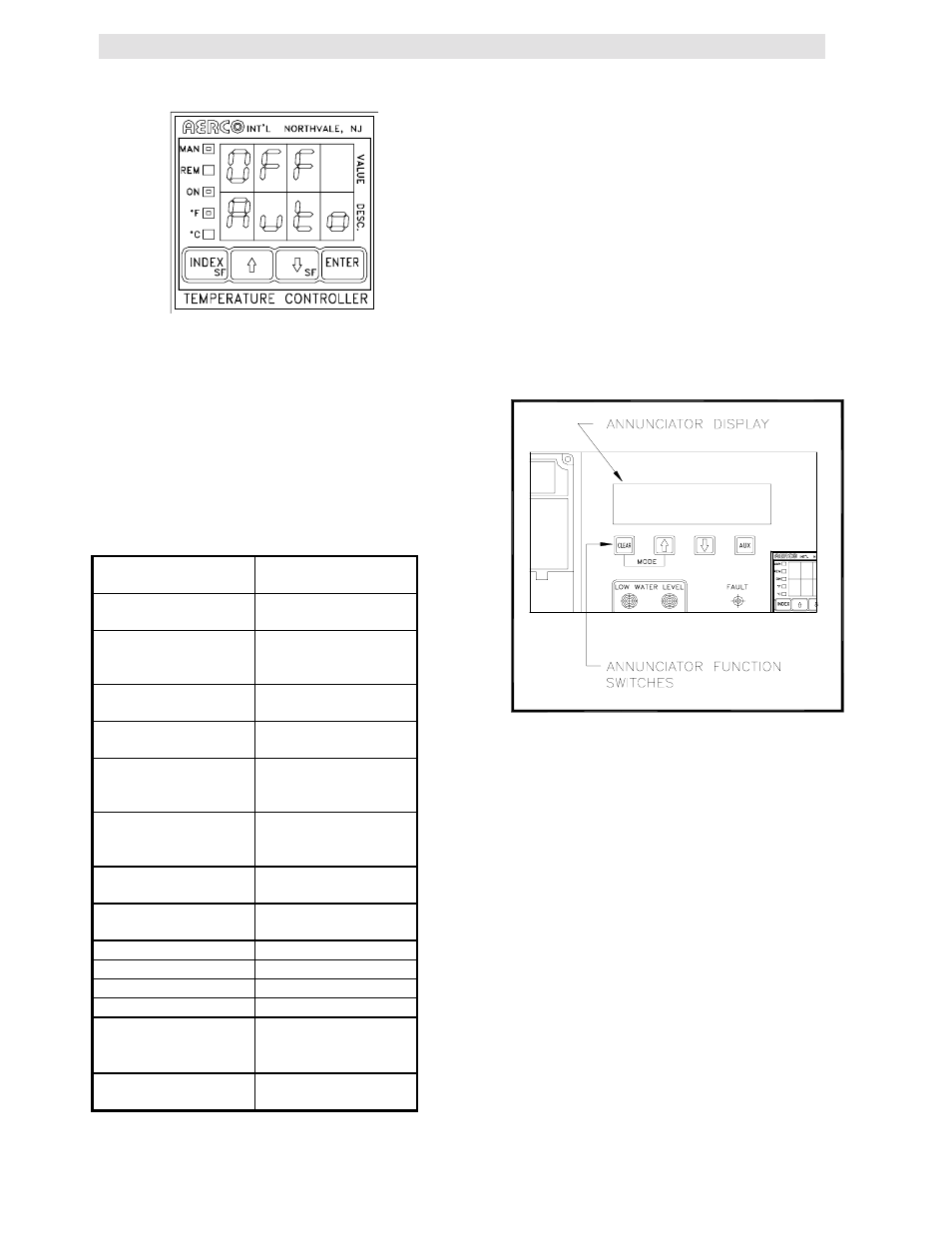
3.5 THE ANNUNCIATOR CIRCUIT
The annunciator consists of the annunciator
circuit board, the front panel LCD display, and 4
function switches (see Fig. 3.8). The annunciator
circuit board is the interface between the LCD
display and the combustion safeguard system. It
monitors the unit during every phase of operation
and prompts the LCD display with start sequence
and fault messages. The function switches are
used to reset the annunciator and gain access to
the annunciator’s three function displays.
Figure 3.8
Annunciator Function Switches and LCD
Display
The annunciator circuit board and LCD display
are not an integral part of the start sequence or
combustion safeguard system. If either should fail
the unit will still operate with no adverse effects.
The annunciator start sequence messages, fault
messages, function switches and function displays
are explained below.
3.5.1 ANNUNCIATOR FUNCTION
DISPLAYS AND SWITCHES
The annunciator has three function displays that
are available to the operator. These are the
MAIN, the CYCLES, and the SET DATE displays.
These displays are accessed using the four
membrane switches located directly under the