Figure 6.11, Grounding terminal location, Figure 6.12 – AERCO KC1000 Heater w/Mod-Box Controller User Manual
Page 39: Burner disassembly diagram, Figure 6.13, Exhaust sensor connector location, Figure 6.14, Blower proof switch wire locations, Maintenance
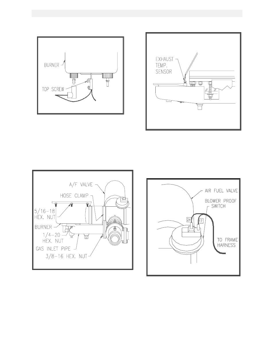
MAINTENANCE
34
Figure 6.11
Grounding Terminal Location
9. Loosen the hose clamp at the air/fuel valve
outlet and slide the clamp back towards the
burner, (see Fig. 6.12).
10. Using a 1/2” socket wrench remove six 5/16-
18 hex nuts supporting the burner, (see Fig.
6.12).
Figure 6.12
Burner Disassembly Diagram
11. Lower the burner while sliding the air hose
off the air/fuel valve. Remove the burner
through the rear of the unit.
12. Disconnect the exhaust temperature sensor
by unscrewing it from the exhaust manifold,
(See Fig. 6.13).
Figure 6.13
Exhaust Sensor Connector Location
13. Disconnect the air/fuel valve wire harness,
the 12 pin connector, from the control panel.
14. Disconnect wires #24 and #17 from the
blower proof switch (See Fig. 6.14).
Figure 6.14
Blower Proof Switch Wire Locations
15. Loosen the hose clamp on the air/fuel valve
inlet and slide the clamp back towards the
blower, (See Fig. 6.15).
- AERClean (12 pages)
- ProtoNode Gateway Rev 1 (with internal LEDs) (64 pages)
- ProtoNode Gateway Rev 3 (with external LEDs) (126 pages)
- Control System (ACS) (144 pages)
- Belimo F6...HD/HDU Series Valve (44 pages)
- Belimo AF120-S US Actuator (9 pages)
- Belimo AMX24-MFT Actuator (9 pages)
- Belimo GKX24-MFT Actuator (9 pages)
- Belimo Motorized Valves Installation (20 pages)
- BMS II BOILER (108 pages)
- BMS II BOILER MODBUS Communication (100 pages)
- BMS 168 (86 pages)
- Boiler Valve Controller (BVC) PRIOR to Serial-12-840-1 (35 pages)
- Boiler Valve Controller (BVC) (38 pages)
- Buffer Tanks (14 pages)
- Combination Control Panel (CCP) (4 pages)
- XPC GATEWAY Communications (193 pages)
- Domestic Water Storage Tank (19 pages)
- Steam Traps (6 pages)
- X100 – Inhibitor (4 pages)
- AM Series Boiler User Manual (156 pages)
- AM Series Boiler Cascade Sequencer Controller (26 pages)
- AM Series Boiler Modbus Interface Manual (18 pages)
- BMK 1.5 LN October 2012 (166 pages)
- BMK 1.5 LN July 2011 (152 pages)
- BMK 1.5 LN June 2010 (123 pages)
- BMK 1.5 LN May 2009 (111 pages)
- BMK 1.5 LN Dual Fuel Feb 2013 (162 pages)
- BMK 1.5 LN Dual Fuel June 2010 (139 pages)
- BMK 1.5 LN Dual Fuel Jan 2009 (126 pages)
- BMK 1500-2000 (188 pages)
- BMK 1500DF (196 pages)
- C-More Control Panel (162 pages)
- BMK 2.0 LN October 2012 (172 pages)
- BMK 2.0 LN Natural Gas (SN G-11-1861 and above) (170 pages)
- BMK 2.0 LN Nat. Gas June 2010 (125 pages)
- BMK 2.0 LN Natural Gas 2008 (111 pages)
- BMK 2.0 LN Nat. Gas for Mass. only (113 pages)
- BMK 2.0 LN Dual Fuel Serial G-11-2402 and UP (160 pages)
- BMK 2.0 LN Dual Fuel Nov 2010 (139 pages)
- BMK 2.0 LN Nat. Gas (112 pages)
- BMK 2.0 LN for Mass. only (114 pages)
- BMK 3.0 LN Dual-Fuel Series Gas Fired Low NOx Boiler System (136 pages)
- BMK 3.0 LN Natural Gas July 2011 (129 pages)
- BMK 3.0 LN Nat. Gas Jan 2011 (129 pages)