Figure 3.9, Combustion safeguard status indicator led location, Figure 3.10 – AERCO KC1000 Heater w/Mod-Box Controller User Manual
Page 19: Water level test and reset switch locations, Control panel operating procedures
CONTROL PANEL OPERATING PROCEDURES
14
3.6 THE COMBUSTION SAFEGUARD
CONTROLLER
The Combustion Safeguard is responsible for
monitoring the safety components during the start
sequence, and after flame is established. It is also
responsible for timing of the purge and ignition
cycles during the start sequence.
The combustion safeguard is located on the left
side of the control panel as shown in Figure 3.9.
There are five status LEDs that indicate the
status of operation. Along with the annunciator,
these are useful as a double check for proper
system operation and troubleshooting. The table
below defines the function of each light. The
reset button located under the LEDs is to reset
the combustion safeguard on lockout.
DESCRIPTION
FUNCTION
POWER
Lights upon power up of
the unit.
PILOT
Lights when there is a call
for heat.
FLAME
Lights once flame has
been detected.
MAIN
Lights after flame has
been detected and
stabilized
ALARM
This lights when the
controller is in a LOCKOUT
condition.
Figure 3.9
Combustion Safeguard Status Indicator LED
Location
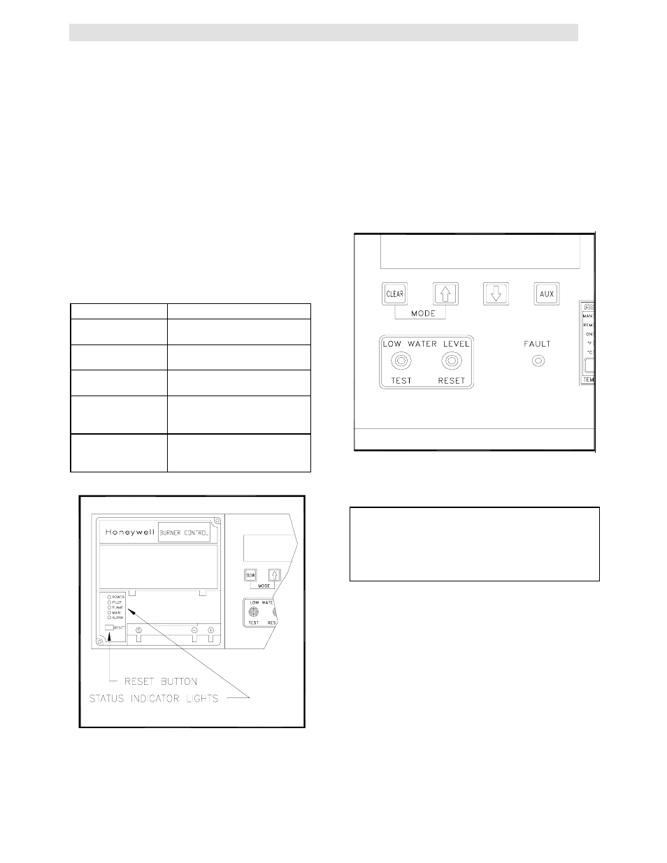
3.7 WATER LEVEL TEST and RESET
SWITCHES
The water level switches are located on the left
side of the panel (see Fig. 3.10). When depressed
the TEST switch simulates a low water level
condition by breaking the connection between the
water level probe and the sensing circuitry. To test
the water level circuitry, depress the test switch for
3 seconds. The unit should fault resulting in the
red fault light blinking and the LED display
indicating LOW WATER LEVEL.
Figure 3.10
Water Level Test and Reset Switch Locations
Note:
Only water level circuitry is tested during the
above test. To determine if the probe is
functioning properly, the water level must be
reduced below the level of the probe.
To reset the unit, depress the water level reset
switch, the annunciator clear button, and if
necessary, the reset button on the combustion
safeguard.
3.8 ON/OFF SWITCH
The ON/OFF switch is located on the right side of
the control box above the temperature controller
(see Figure 3.1). It is part of the start string and
must be in the ON position to enable the unit to
fire. When the switch is in the ON position and
illuminated, it is indicating that the start limit
string, consisting of water temperature, gas
pressure, water level, and the interlock is
satisfied. The unit, at this point, is in standby
mode and ready to run.