AERCO KC Standard to Low NOx Convertion Instructions User Manual
Page 41
41
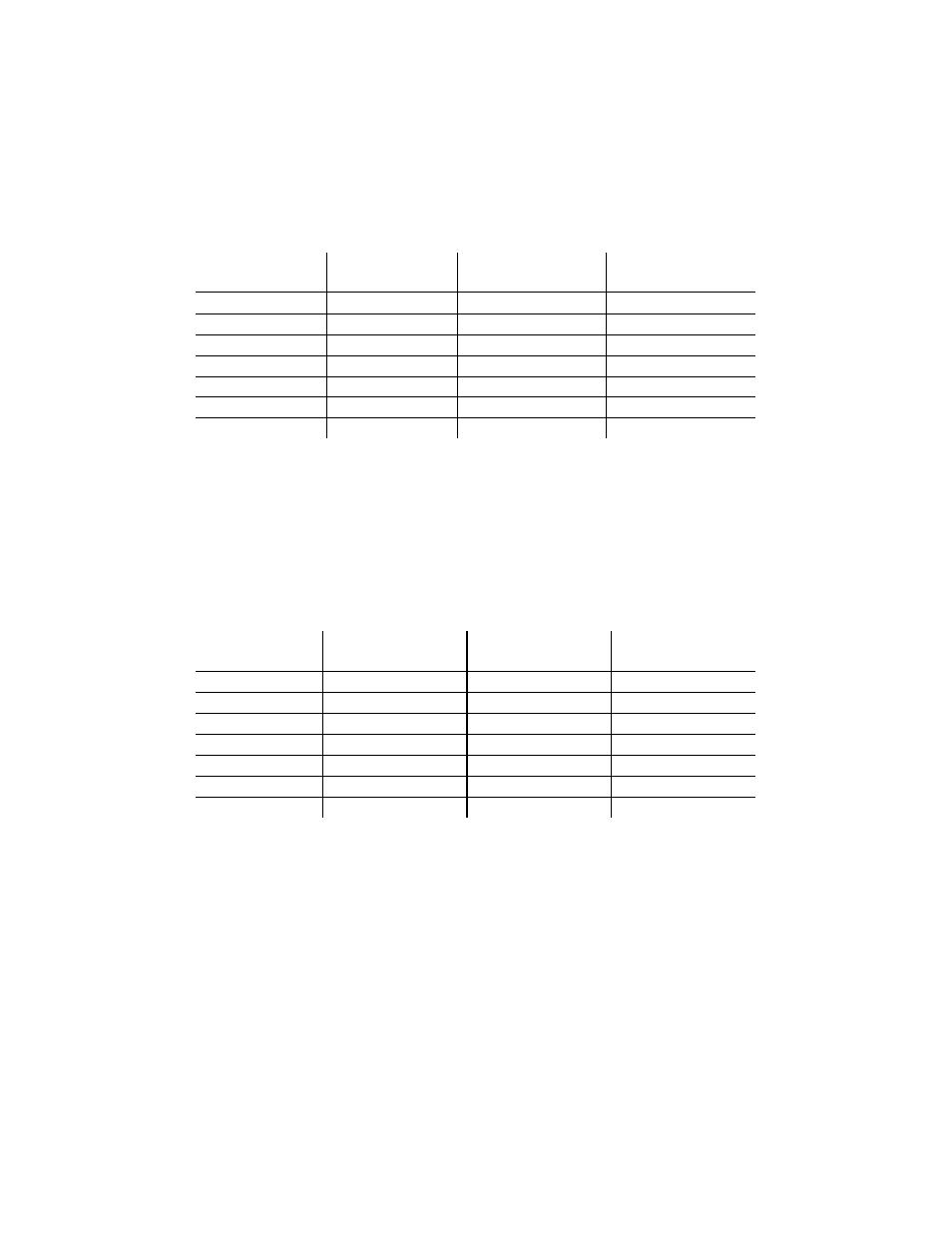
15. Oxygen levels at the 10% (1.4V) firing rate should be as shown in Table 5. Also, ensure that
the CO and NOx readings do not exceed the values shown. No adjustment should be
necessary. Contact the Factory if the oxygen, CO or NOx levels are not within the specified
ranges.
Table 5
Combustion Oxygen Levels for a 10% (1.4V) Firing Rate
Inlet Air
Temp
Oxygen
(± 0.2%)
Carbon
Monoxide
*NOx
40°F
<10%
<100 ppm
<20 ppm
50°F
<10%
<100 ppm
<20 ppm
60°F
<10%
<100 ppm
<20 ppm
75°F
<10%
<100 ppm
<20 ppm
85°F
<10%
<100 ppm
<20 ppm
90°F
<10%
<100 ppm
<20 ppm
100°F
<10%
<100 ppm
<20 ppm
*Tabulated data are uncorrected ppm NOx values and will be less than or equal to 30 ppm of NOx
when corrected to 3% oxygen.
16. Change the firing rate to 100%. After the combustion analyzer has settled, compare the
measured oxygen level with the levels in Table 6.
Table 6
Combustion Oxygen Levels for a 100% (5.0V) Firing Rate
Inlet Air
Temp
Oxygen
(±0.2%)
Carbon
Monoxide
*NOx
40°F
8.8 %
<100 ppm
<20.3 ppm
50°F
8.1 %
<100 ppm
<21.4 ppm
60°F
7.5 %
<100 ppm
<22.5 ppm
75°F
6.5 %
<100 ppm
<24.1 ppm
85°F
5.8 %
<100 ppm
<25.3 ppm
90°F
5.3 %
<100 ppm
<26.1 ppm
100°F 4.8
% <100
ppm
*Tabulated Data are uncorrected ppm NOx values and will be less than or equal to 30 ppm of
NOx when corrected to 3% oxygen.
17. If the measured oxygen reading is below the oxygen range in Table 6, loosen the two bolts
that secure the inlet air shutter to the unit using a 7/16” wrench (see Figure 4.4). Open the
shutter 1/4” to 1/2” to increase the oxygen level, then tighten the nuts.
18. Wait for the analyzer to settle then compare the new oxygen reading to Table 6. Repeat the
inlet air shutter adjustment until the oxygen is within the specified range. Also, ensure that the
CO and NOx emissions do not exceed the values shown. Firmly tighten the inlet air shutter
locking nuts when finished.