AERCO KC Standard to Low NOx Convertion Instructions User Manual
Page 40
40
NOTE
Always approach a firing rate percentage from the same direction, (i.e., 100%
to 25%, 25% to 20%, etc.). Whenever going to an increased firing rate from
below (i.e., 25% to 30%), first go above and then back down to the desired
firing rate. This is necessary due to hysteresis in the air/fuel stepper motor.
Hysteresis causes the air/fuel valve to stop in a slightly different position if the
firing rate percentage is approached from below or above. This results in a
difference in oxygen readings for the same firing rate percentage causing
unnecessary recalibration.
8. Allow enough time for the combustion analyzer to settle. Compare the measured oxygen level
to the oxygen range for intake air temperature in Table 4. Also, ensure that the carbon
monoxide (CO) and nitrogen oxide (NOx) readings do not exceed the values shown.
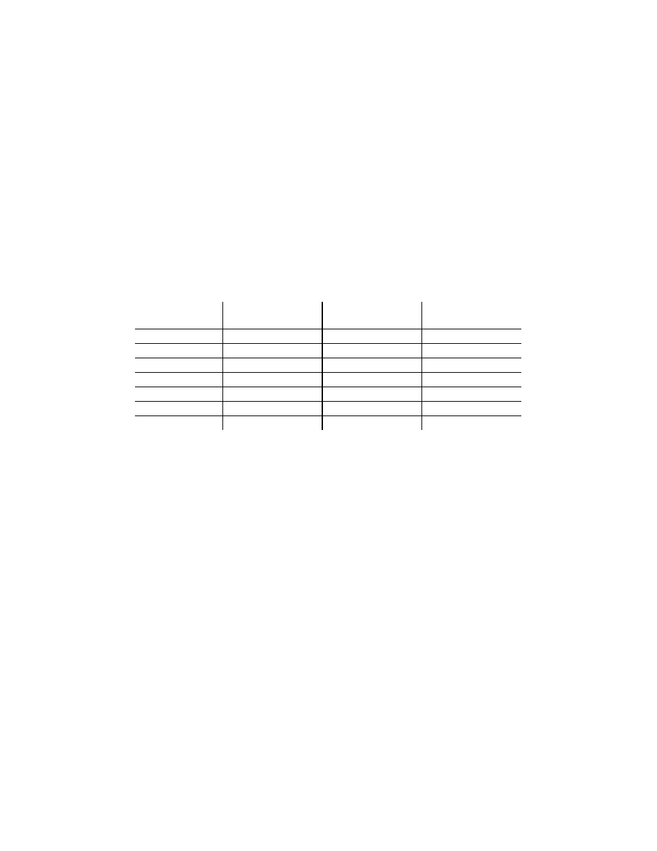
Table 4
Combustion Oxygen Levels for a 25% (2.0V) Firing Rate
Inlet Air
Temp
Oxygen
(±0.2%)
Carbon
Monoxide
*NOx
40°F
6.7 %
<100 ppm
<23.8 ppm
50°F
6.5 %
<100 ppm
<24.1 ppm
60°F
6.3 %
<100 ppm
<24.4 ppm
75°F
6.0 %
<100 ppm
<24.9 ppm
85°F
5.7 %
<100 ppm
<25.4 ppm
90°F
5.6 %
<100 ppm
<25.6 ppm
100°F
5.4 %
<100 ppm
<25.9 ppm
*Tabulated data are uncorrected ppm NOx values and will be less than or equal to 30 ppm of
NOx when corrected to 3% oxygen.
9. If the measured oxygen level, CO and NOx emissions are within the ranges shown in Table 4,
no adjustment is necessary. Proceed to step 14.
10. If the measured oxygen level is below the range in Table 4, rotate the differential regulator
adjustment tool counterclockwise 1/4 to 1/2 revolution to decrease gas flow.
11. Wait for the combustion analyzer to settle, then compare the new oxygen reading to Table 4.
Repeat adjustment until oxygen is within the specified range.
12. If the measured oxygen level is above the oxygen range in Table 4, rotate the differential
regulator adjustment tool clockwise 1/4 to 1/2 revolution to increase gas flow.
13. Wait for the analyzer reading to settle, then compare the new reading to Table 4. Repeat
adjustment until oxygen is within the specified range.
NOTE
Adjust only the differential regulator at 25% (2.0V) control signal; do not adjust
the air shutter.
14. Once the oxygen level is within the specified range at 25% (2.0V), change the firing rate to
10% (1.4V).