AERCO KC Standard to Low NOx Convertion Instructions User Manual
Page 20
20
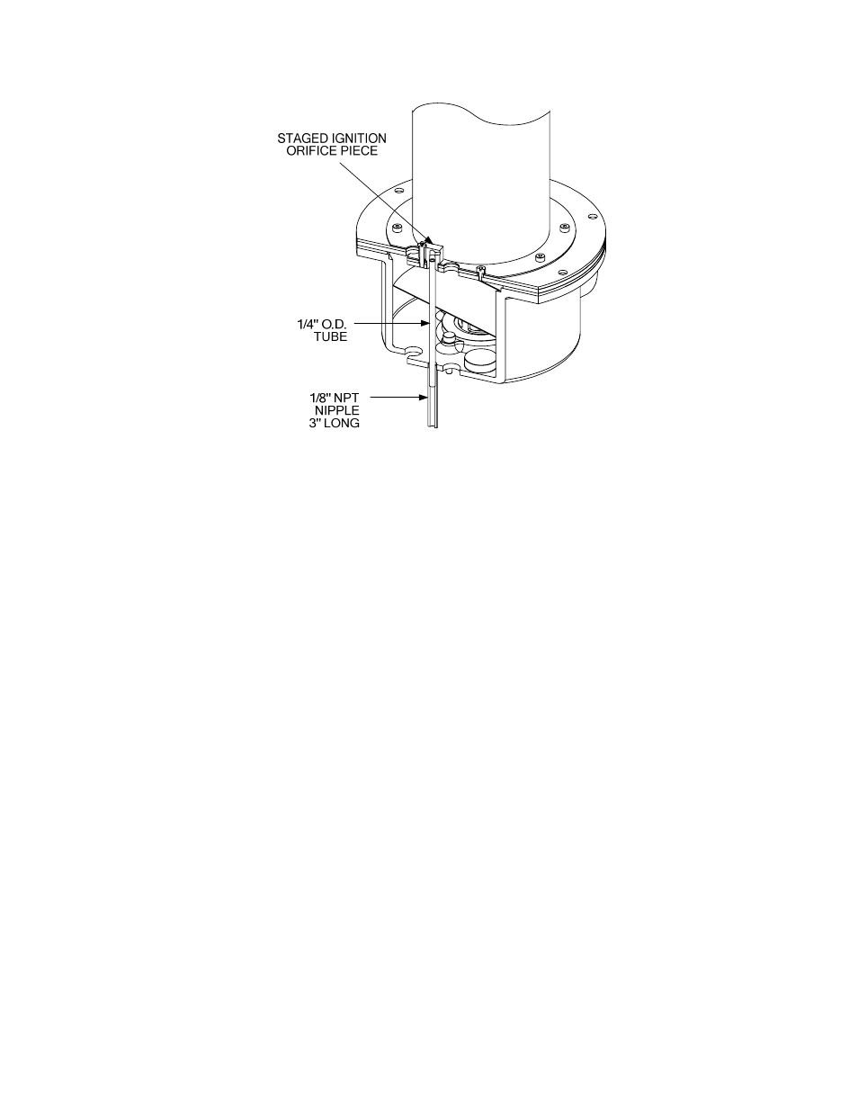
Figure 17. Installation of Staged Ignition Tube and Nipple
5.
Reinstall the Exhaust Manifold insulation (Figure 4) using three 1/4-20 screws and fender
washers.
6.
Reinstall the modified Air/Fuel Valve (Figure 18) as follows:
(a) Connect the blower-to-valve air hose and clamp at the Air/Fuel Valve inlet as shown in
Figure 18. Do Not tighten the hose clamp at this time.
(b) Ensure that the flange O-ring is installed between the Air/Fuel Valve gas inlet flange and
the Differential Gas Pressure Regulator outlet flange.
(c) Using two 9/16” wrenches, secure the Air/Fuel Valve to the Differential Gas Pressure
Regulator with two 3/8-16 bolts and hex nuts.
(d) Tighten the hose clamp on the blower-to-valve air hose at the Air/Fuel Valve inlet.
(e) Using an 11/16” wrench, secure the feedback tube between the Air/Fuel Valve and
Regulator by tightening the two compression fittings (Figure 18).
(f) Reconnect the two wire leads to the Blower Proof Switch.
(g) Reconnect the Air/Fuel Valve wiring harness to the Control Box.
7.
Install the Gas Inlet Pipe (Figure 18) between the Air Fuel Valve gas outlet and the Low NOx
Burner gas inlet as follows:
(a) Insert flange O-rings in the inlet and outlet sides of the gas pipe.
(b) Position the Gas Inlet Pipe so it is aligned with the 1/4-20 studs on the Burner and the
Air/Fuel Valve gas outlet flange.