AERCO KC Standard to Low NOx Convertion Instructions User Manual
Page 21
21
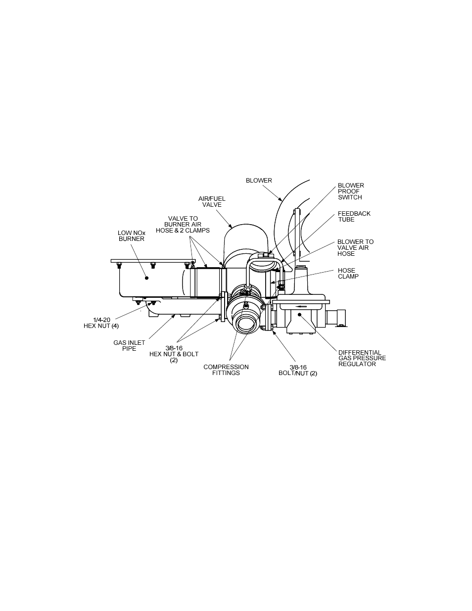
(c) Secure the Gas Inlet Pipe to the Air/Fuel Valve with two 3/8-16 bolts and hex nuts.
(d) Secure the Pipe to the Burner with four 1/4-20 hex nuts.
(e) Reinstall the valve-to-burner air hose and clamps between the Air/Fuel Valve outlet and
Burner inlet. Tighten both clamps.
NOTE
Figure 18 shows the installation details for both the modified Air/Fuel Valve
and the Gas Inlet Pipe. Install these items in the order specified in steps 6
and 7.
Figure 18. Air/Fuel Valve and Gas Inlet Pipe Installation
8.
The next item to be installed is the new Staged Ignition Assembly shown in Figure 19. As this
Figure shows, there are two versions of this assembly; one for use with Siemens SSOVs (part
no. 124867) and one for use with Honeywell SSOVs (part no. 124983). Mechanically, the
outlet side of both Staged Ignition Assembly models connect to the Low NOx Burner.
However, the inlet side connections of Staged Ignition Assembly models differ as follows:
• Staged Ignition Assembly 124867 (used with Siemens SSOVs) inlet side connects to the
downstream port directly on the Siemens SSOV.
• Staged Ignition Assembly 124983 (used with Honeywell SSOVs) inlet side connects to the
port on the gas cock located downstream of the Honeywell SSOV.
Electrically, the solenoid valve on each of these assemblies is connected to the KC wiring
harness power leads going to the ignition transformer. The mechanical connections are
provided in steps 9, 10 and 11. The electrical connections are provided in step 13.