AERCO KC Standard to Low NOx Convertion Instructions User Manual
Page 23
23
NOTE
The 1/8” street elbow shown in Figure 19 was previously removed in step 4(f)
and attached to the 3” nipple on the Low NOx Burner Shell.
9.
The outlet side connection for the Staged Ignition Assembly is the same regardless which type
of SSOV (Siemens or Honeywell) is installed on the KC1000. Proceed as follows:
(a) Loosen the 1/4“ NPT union on the Staged Ignition Assembly (Figure 19) provided in the kit
and separate the 9” nipple and 1/4” to 1/8” reducing coupling from the assembly.
(b) Connect the reducing coupling to the 1/8” street elbow already attached to the Low NOx
Burner (Figure 20).
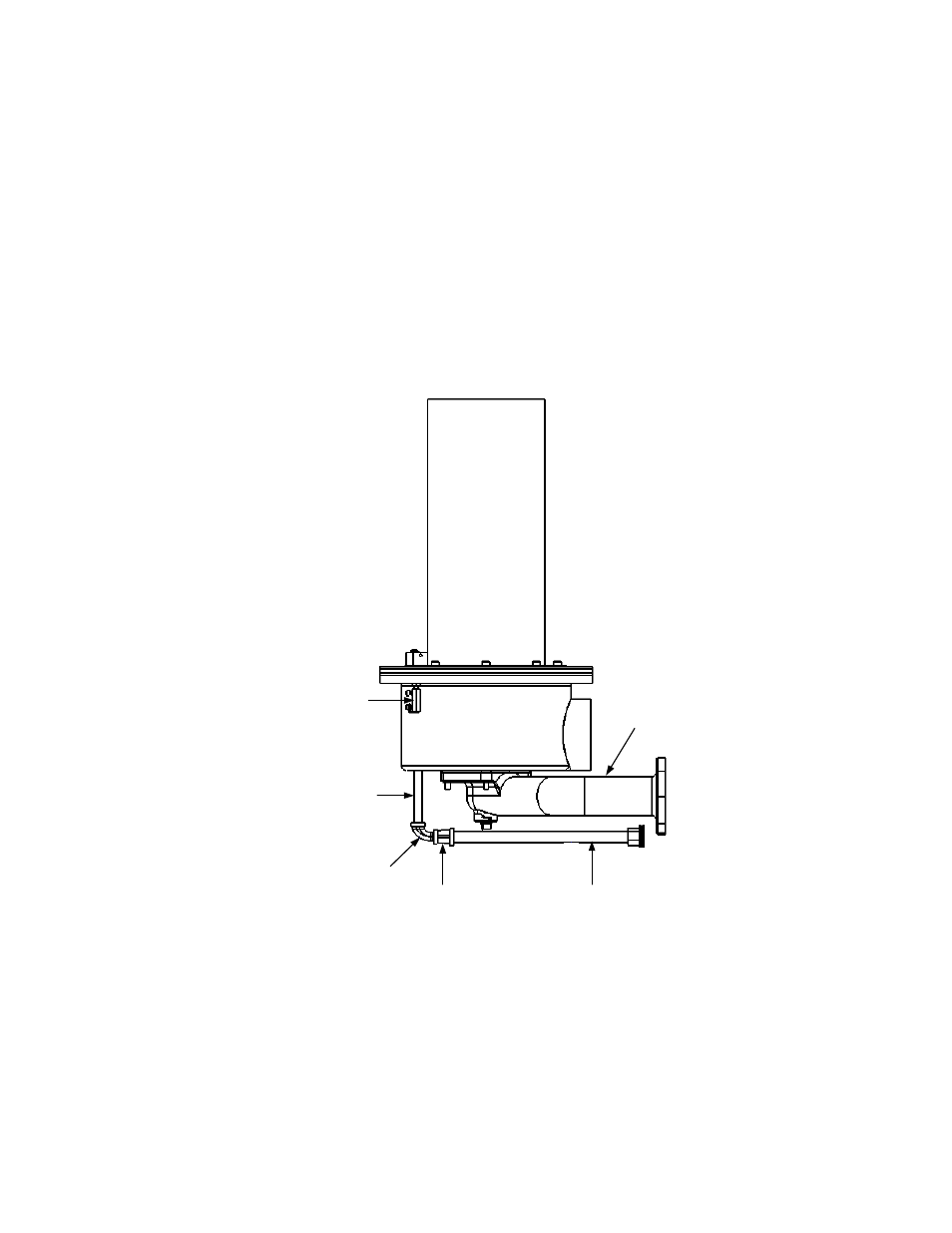
GAS INLET
PIPE
1/4" NPT NIPPLE
(9" LONG)
REDUCING
COUPLING
STREET
ELBOW
1/8" NPT
NIPPLE
(3" LONG)
GROUND
CONNECTOR
Figure 20. Staged Ignition Assembly Outlet Side Connection
10.
The inlet side connection for the Staged Ignition Assembly depends on which type of SSOV
(Siemens or Honeywell) is installed in the KC1000. Proceed as follows:
(a) Refer to Figure 19. For the Staged Ignition Assembly provided in the kit, disconnect the
1/2” flex gas hose at the inlet side from the 1/2” to 1/4” reducing coupling shown in Figure
19 for the applicable assembly.