4 propane combustion calibration, 5 unit reassembly, Initial start-up – AERCO KC1000 Boiler equipped with C-More version 3.04 User Manual
Page 37
INITIAL START-UP
NOTE:
4-5
Adjust the inlet air shutter only at 100% valve
position. Do not adjust the differential pressure
regulator.
28. Change the valve position to 30%. Allow
time for the combustion analyzer to settle.
Check the measured oxygen reading to
insure that it is still within the range as per
Table 1.
29. Continue this procedure until all oxygen
levels are within the ranges specified in
Tables 1, 2 and 3.
30. Record all readings on the AERCO start-up
sheet provided with each unit. Proceed to
paragraph 4.5.
4.4 PROPANE COMBUSTION
CALIBRATION
For propane units it will be necessary to install
an additional 8” W.C. This manometer will be
used to measure the pressure drop across the
air/propane mixing orifice. After performing the
setup procedures in paragraphs 4.2.2 through
4.2.4, install the 8” W.C. manometer as
described in steps 1, 2 and 3 which follow.
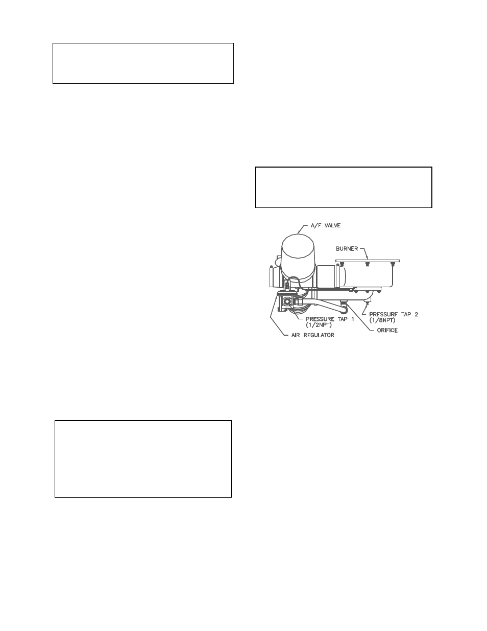
1. Refer to Fig. 4.5 and remove the 1/8” NPT
plug from the gas inlet pipe ahead of the
burner. Install a 1/8” NPT barbed fitting.
2. Remove the 1/2” NPT plug from the tee
located after the air pressure regulator and
install a 1/2” barbed fitting (see Fig. 4.5).
3. Attach the 8” W.C. manometer to the barbed
fittings installed in steps 1, and 2.
NOTE:
The combustion calibration data in Tables 1, 2
and 3 apply to both natural gas and propane
units. Therefore, refer to these Tables when
performing propane combustion calibration. Note
that Table 2 checks the oxygen and carbon
monoxide levels at a valve position of 16% for
propane instead of the 13% used for natural gas.
4. While performing the combustion calibration
procedure in paragraph 4.3, measure the
pressure drop across the air/propane mixing
orifice using the 0-8” W.C. manometer.
5. This reading should remain constant at 3.8”
to 4.0” W.C. throughout the operating range.
6. If the pressure drop is not within this range,
remove the cap from the air pressure
regulator.
7. Using a flat blade screwdriver adjust the
regulator until 3.8” to 4.0” W.C. is obtained.
Clockwise will increase the reading and
counterclockwise will decrease the reading.
8. It adjustments are made to this regulator, it
will be necessary to recheck oxygen
readings at 16%, 30%, and 100% valve
positions.
NOTE:
After an adjustment is made to the air regulator,
the cap must be replaced and securely tightened
to obtain an accurate reading
Figure 4.5
Propane Air Differential Pressure Taps
4.5 UNIT REASSEMBLY
Once combustion calibration is set properly, the
unit can be reassembled for permanent
operation as follows:
1. Set
the
ON/OFF switch to the OFF position.
Disconnect the AC power supply from the
unit.
2. Shut off the gas supply to the unit.
3. Remove the differential pressure regulator
cap and cap gasket (see Figure 4.3).
4. Apply a drop of silicone adhesive to the
regulator adjusting screw to lock its setting.
5. Reinstall the regulator cap and gasket on the
regulator. Tighten the cap using a
screwdriver or wrench.