8 start sequence, Control panel operating procedures – AERCO KC1000 Boiler equipped with C-More version 3.04 User Manual
Page 30
CONTROL PANEL OPERATING PROCEDURES
3.8. START SEQUENCE
When the Control Box ON/OFF switch is set to
the ON position, it checks all pre-purge safety
switches to ensure they are closed. These
switches include:
• Safety Shut-Off Valve Proof of Closure
(POC) switch
• Low Water Level switch
• High
Water
Temperature
switch
• High Gas Pressure switch
• Low Gas Pressure switch
If all of the above switches are closed, the
READY
light above the ON/OFF switch will light
and the unit will be in the Standby mode.
When there is a demand for heat, the following
events will occur:
NOTE:
If any of the Pre-Purge safety device switches
are open, the appropriate fault message will be
displayed. Also, the appropriate fault messages
will be displayed throughout the start sequence,
if the required conditions are not observed.
1. The DEMAND LED status indicator will light.
2. The unit checks to ensure that the proof of
closure switch in the Safety Shut-Off Valve
(SSOV) is closed (Figure 3-3).
Figure 3-3.
Safety Shut-Off Valve
3. With all required safety switches closed, a
purge cycle will be initiated and the following
events will occur:
(a) Blower relay energizes and turns on
blower.
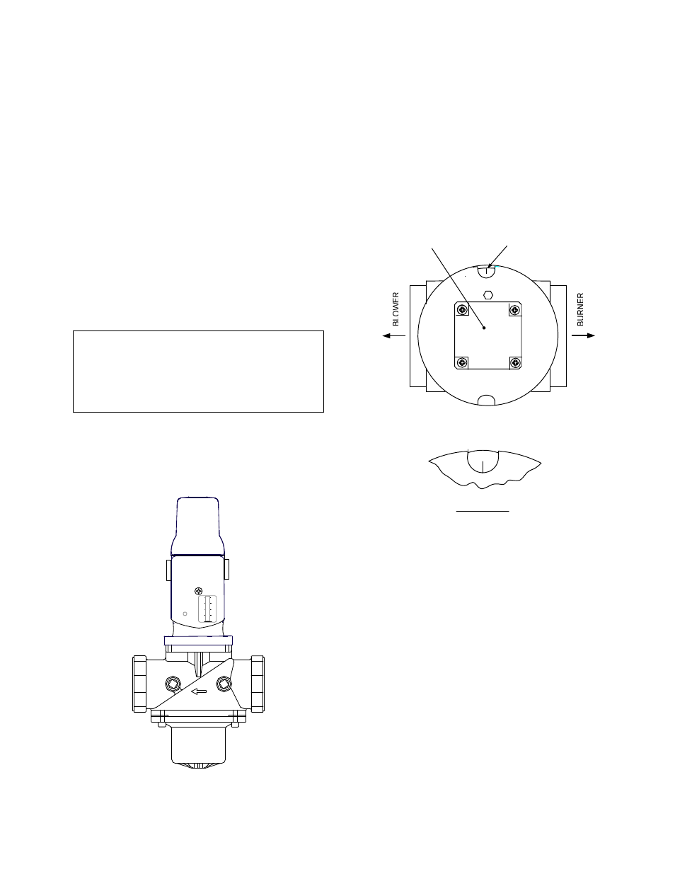
(b) Air/Fuel Valve rotates to the full-open
purge position and closes purge position
switch. The dial on the Air/Fuel Valve
(Figure 3-4) will read 100 to indicate that
the valve is full-open (100%).
STEPPER
MOTOR
DETAIL "A"
DIAL
(DETAIL “A”)
100
Figure 3-4.
Air/Fuel Valve In Purge Position
4. Next, the blower proof switch (Figure 3-5)
closes and the display will show Purging and
indicate the elapsed time of the purge cycle
in seconds. The normal (default) time for the
purge cycle is 7 seconds.
3-8