3 pressure relief and drain valve installation, 4 temperature/pressure indicator, Installation – AERCO KC1000 Boiler equipped with C-More version 3.04 User Manual
Page 13
INSTALLATION
Every boiler plant must have a source of make-
up water to it. As with any closed loop hydronic
system, air elimination and expansion equip-
ment must be provided as part of the overall
installation. All piping MUST include ample
provision for expansion.
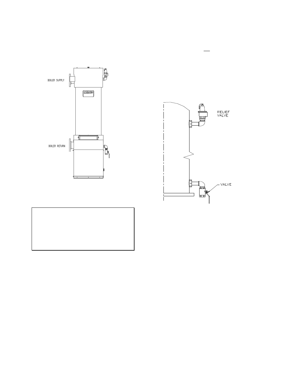
Figure 2.3
Supply and Return Location
NOTE:
The maximum working pressure for
installations within the Province of Alberta is
87 psig. Therefore a pressure relief valve
with a setting of 75 psig (or lower) should be
installed for these installations. See Drawing
AP-A-863 in Appendix F.
2.3.3 PRESSURE RELIEF AND DRAIN
VALVE INSTALLATION
An ASME rated Relief Valve is supplied with
each unit. The supplied pressure relief valve
setpoint will be 30, 50, 75, 100, or 150
psig as
ordered from the factory. Install the pressure
relief valve in the tapping provided opposite the
system supply connection, (see Figure 2.4). The
pressure relief valve should be piped in the
vertical position
using the fittings supplied. A
suitable pipe compound should be used on the
threaded connections, and excess should be
wiped off to avoid getting any into the valve
body. The discharge from the relief valve should
be piped to within 12 inches of the floor to
prevent injury in the event of a discharge.
The relief piping must be full size without
reduction. No valves, restrictions, or other
blockages should be allowed in the discharge
line. In multiple unit installations the relief valve
discharge lines must not be manifolded,
(connected), together. Each must be individually
run to a suitable discharge location. The drain
valve provided should be installed on the right
hand side of the unit towards the bottom of the
shell. The valve should be pointed in the down
position, (see Figure 2.4).
Figure 2.4
Relief and Drain Valve Location
2.3.4 TEMPERATURE/PRESSURE
INDICATOR
The unit is supplied with one of two styles of
Temperature/Pressure Indicators that must be
installed in the tapping on the supply flange of
the unit (see Figures. 2.5a and 2.5b). A suitable
pipe compound should be used sparingly to the
threaded connection.
2-3