5 condensate piping, 4 gas supply piping, Installation – AERCO KC1000 Boiler equipped with C-More version 3.04 User Manual
Page 14
INSTALLATION
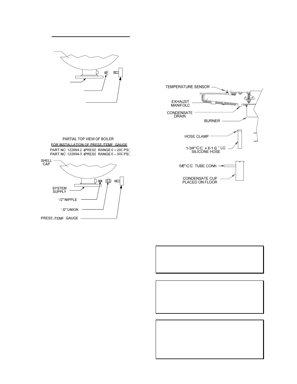
SHELL
CAP
PARTIAL TOP VIEW OF BOILER
FOR INSTALLATION OF PRESS./TEMP. GAUGE
PART NO. 122994-1 (PRESS. RANGE 0 – 75 PSI)
SYSTEM
SUPPLY
1/2" x 1 /4"
REDUCING BUSHING
PRESS./TEMP. GAUGE
Figure 2.5a
Pressure /Temperature Gauge Installation
Figure 2.5b
Pressure/Temperature Gauge Installation
2.3.5 CONDENSATE PIPING
The KC Boiler is designed to condense.
Therefore, the installation site must include
suitable provisions for condensate drainage or
collection. A stainless steel condensate cup is
separately packed within the unit’s shipping
container. To install the condensate cup,
proceed as follows:
1. Remove the left side panel and only the left
half of the rear cover to provide access to the
exhaust manifold and burner (Figure 2.6).
2. Insert the 1-3/4 inch manifold drain hose into
the condensate cup. Allow the cup to rest on
the floor directly beneath the manifold drain
hole (Figure 2.6).
3. Attach a length of 3/4 inch I.D. polypropylene
tubing to the condensate cup drain tube and
route it to a floor drain. If a floor drain is not
available, a condensate pump can be used to
remove the condensate to drain. The
condensate drain line must be removable for
routine maintenance. Therefore, DO NOT hard-
pipe.
4. Replace the rear cover and side panel on the
unit.
Figure 2.6
Condensate Drain System Location
2.4. GAS SUPPLY PIPING
The AERCO
Gas Fired Equipment Gas Compo-
nents and Supply Design Guide (GF-1030) must be
consulted before any gas piping is designed or
started.
WARNING!
DO NOT USE MATCHES, CANDLES,
FLAMES OR OTHER SOURCES OF
IGNITION TO CHECK FOR GAS LEAKS
.
CAUTION!
Soaps used for gas pipe leak testing can be
corrosive to metals. Piping must be rinsed
thoroughly with clean water after leak
checks have been completed.
NOTE:
All gas piping must be arranged so that it
does not interfere with removal of any
cover, inhibit service or maintenance, or
prevent access between the Unit and walls,
or another unit.
2-4