AERCO BMK 6000 User Manual
Page 78
Benchmark 6000 Boiler Installation, Operation & Maintenance Manual
CHAPTER 6 – SAFETY DEVICE TESTING
Page 78 of 210
AERCO International, Inc. • 100 Oritani Dr. • Blauvelt, NY 10913
OMM-0086_0D
03/20/14
Ph.: 800-526-0288
GF-133
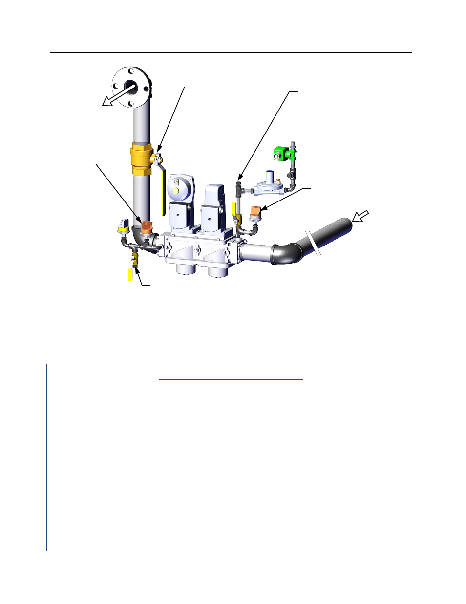
Figure 6-1A: Low Gas Pressure Switch Locations & Test Point Locations
The upstream Low Gas Pressure switch is set at 8.6” W.C. and is tested as follows:
Low Gas Pressure Fault Test
1. Remove the 1/4“ plug from the Tee at the Low Gas Pressure switch shown in Figure 6-
1A.
2. Install a NPT-to-barbed fitting and connect a 0 – 16“ W.C. manometer where the 1/4" plug
was removed.
3. Open the external gas supply ball valve upstream of the unit.
4. Place the unit in Manual Mode and adjust the Air/Fuel Valve position (% open) to 50%.
5. While the unit is firing, slowly close the external gas supply shut-off valve.
6. The unit should shut down and display a GAS PRESSURE fault message at approximately
8.5” W.C. The FAULT indicator should also start flashing.
7. Fully open the external gas supply ball valve and press the CLEAR button on the Control
Box.
8. The fault message should clear and the FAULT indicator should go off. The unit should
restart.
TO AIR/FUEL
VALVE
GAS
INLET
HIGH GAS
PRESSURE
SWITCH
(10.5” W.C.)
MANUAL
SHUT-OFF
VALVE
TEE WITH 1/4" NPT PLUG
(Install manometer here for
Upstream Low Gas Pressure
test)
UPSTREAM LOW GAS PRESSURE
SWITCH (8.5” W.C.)
BALL VALVE WITH NPT 1/4" PLUG
(Install manometer here for Downstream Low Gas Pressure test)