10 field control wiring – AERCO BMK 1500-2000 User Manual
Page 26
Benchmark 1500 - 2000 Boilers
CHAPTER 2 – INSTALLATION
Page 26 of 188
AERCO International, Inc. • 100 Oritani Dr. • Blauvelt, NY 10913
OMM-0097_0D
Ph.: 800-526-0288
GF-142
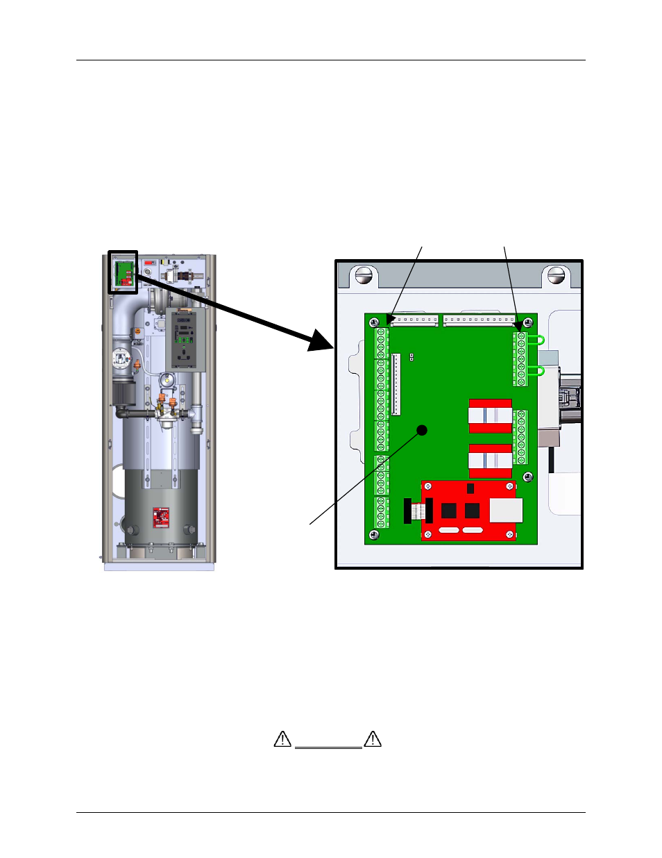
2.10 FIELD CONTROL WIRING
Each unit is fully wired from the factory with an internal operating control system. No field control
wiring is required for normal operation. However, the C-More Control system used with all
Benchmark units does allow for some additional control and monitoring features. Wiring
connections for these features are made on the Input/Output (I/O) board located behind the
removable front panel assembly of the unit. The I/O board is located in the upper-left portion on
the front of the unit as shown in Figure 2-11. The I/O board terminal strip connections are shown
in Figure 2-12. All field wiring is installed from the rear of the panel by routing the wires through
one of the four bushings provided on the sides of the I/O board.
Refer to the wiring diagram provided below the I/O Box (Figure 2-12) when making all wiring
connections.
Figure 2-11: Input/Output (I/O) Box Location
NOTE
Use Figure 2-12 to determine the functions of the I/O PCB
connections. Do not use the silkscreened labels on the PCB itself,
as these may not match the function names.
There is a diagram of the connection functions on the cover of the
I/O Box as well.
DO NOT make any connections to the I/O Box terminals labeled
“NOT USED”. Attempting to do so may cause equipment damage.
CAUTION
I/O PCB
BOARD
TERMINAL STRIPS