1 overview and specifications, 1 component names and units, 1-1 main system and cables – KEYENCE SL-CHS Series User Manual
Page 9
Chapter 1 Overview and Specifications
1-1
1
ENGLISH
1 Overview and Specifications
1-1 Component Names and Units
This section describes each part of the SL-CHS Series and optional units.
For component locations and appearances
,
➮ see the “1-4 Dimensional Drawings” (page 1-7).
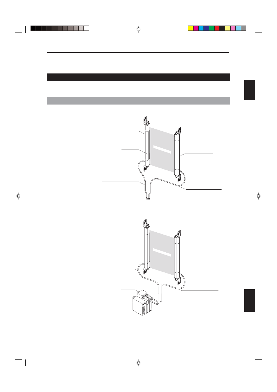
1-1-1 Main System and Cables
When using the SL-CHS stand-alone
When combining the SL-CHS with a controller
SL-CHS Series + SL-U2 (Dedicated power supply unit) + SL-R11 (Intelligent safety relay unit)
SL-U2: The UL certified or recommended dedicated power supply unit
SL-R11:The safety relay is built-in. This is connected to the SL-CHS by a special connector.
T: Transmitter
R: Receiver
Detection zone
SL-CHS Series Transmitter
Status indicator
(on both sides)
SL-P7N/P (7 m (22.97 ft.)) cable
for transmitter (gray)
SL-P7N/P (7 m (22.97 ft.)) cable
for receiver (black)
SL-CHS Series Receiver
SL-U2
SL-R11
SL-PC5P (5 m (16.4 ft.)) cable for transmitter (gray)
* 10 m(32.81 ft.) SL-PC10P cable
SL-PC5P (5 m(16.4 ft.)) cable
for receiver (black)
* 10 m(32.81 ft.) SL-PC10P cable
Detection zone