5-4 npn and pnp outputs, 5-5 series connection, 5-6 light interference prevention connection – KEYENCE SL-CHS Series User Manual
Page 21: English, Chapter 1 overview and specifications
Chapter 1 Overview and Specifications
1-13
1
ENGLISH
1-5-4 NPN and PNP Outputs
The SL-CHS has two types of OSSD outputs: PNP output and NPN output. KEYENCE has a PNP output
cable and a NPN output cable for use as dedicated OSSD output cables, The OSSD output type can be
switched by selecting one of these cables.
These cables are identified by the color of the connector connected to the SL-CHS and by the tag attached
to the cable as follows.
Cable Type
Connector color
PNP output cable
Black
NPN output cable
Grey
1-5-5 Series Connection
2 or more sets of the SL-CHS Series can be connected by using a pair of dedicated series connection cables
to form a light curtain with a single set of output logic (see figure below).
In this instruction manual, the unit that is directly connected to the power supply unit and that supplies power
to the sensor units connected in series is called the “Unit 1,” and the next unit that is connected to the Unit 1
using a dedicated series connection cable are called “Unit 2.” Further, when used in serial connections the
device connected after “Unit 2” is “Unit 3”, and the next device is “Unit 4”.
For details regarding the connection method,
refer to “3-5 Series Connection” (
➮ page 3-4).
Unit 2
Unit 1
Tr
ansmitter
Receiv
er
Tr
ansmitter
Receiv
er
Synchronization cable
Output
(Orange)
(Orange/black)
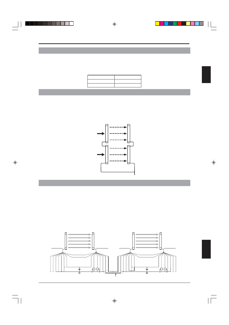
1-5-6 Light Interference Prevention Connection
As shown in the figures below, using the light interference prevention function allows the parallel connection
of 2 or more sets of the SL-CHS Series and prevents light interference in the respective unit of the SL-CHS
Series. This connection method is called a light interference prevention connection. (See the figure below.)
In this instruction manual, the unit that is connected parallel to the SL-CHS via a light interference prevention
cable and that transmits a signal for light interference prevention is called the “main unit”. The units that
receive the light interference prevention signal from the main unit and operate in accordance with this signal
are called “sub unit.”
When making a light interference prevention connection, one pair of SL-CHS Series units must be set as the
main unit, and the other as the sub unit.
For details regarding the connection method,
refer to “3-6 Connection for Light Interference Prevention” (
➮
page 3-5). (PNP wiring shown below.)
Main unit
Sub unit
FSD1 FSD2
24V DC
Cable/gray
Cable/black
Shield
Shield
Light interference prevention
cable (input /-) (gray/black)
Light interference prevention
cable (output /+) (gray)
Light interference prevention
cable (input /+) (gray)
Light interference prevention
cable (output /-) (gray/black)
0 V (blue)
0 V (Blue)
Main/sub switching
input (pink)
Test input (purple)
OSSD2 (white)
OSSD1 (black)
+24 V (brown)
+24 V (brown)
RS-485(B)orange/black
RS-485(A) orange
Transmitter
Receiver
FSD1 FSD2
24V DC
Cable/gray
Cable/black
Shield
Shield
Light interference prevention
cable (output /+) (gray)
Light interference prevention
cable (input /+) (gray)
Light interference prevention
cable (output /-) (gray/black)
0 V (blue)
0 V (Blue)
Main/sub switching
input (pink)
Test input (purple)
OSSD2 (white)
OSSD1 (black)
+24 V (brown)
+24 V (brown)
RS-485(B)orange/black
RS-485(A) orange
Transmitter
Receiver
2-wire shielded cable
Light interference prevention
cable (input /-) (gray/black)