English – KEYENCE SL-CHS Series User Manual
Page 46
Chapter 4 Checklist
4
English
ENGLISH
❏
If 2 or more sets of the SL-CHS Series are used - a series connection or light interference preven-
tion connection is used to prevent light interference.
See “3-6 Connection for Light Interference
Prevention” (
➮ page 3-5) and take measures to prevent light interference among each SL-CHS
units.
3.
Check Using an Operation Test with the Machine Stopped
With the machine stopped, turn on the power of the SL-CHS and carry out the following tests using the
test piece included in the package. If you are using any of models SL-CHS**L having the detection
capability of 45 mm diameter, prepare a test piece having a diameter of 45 mm at customer's side, and
implement the test. If the floating blanking function is active, do not use the attached test piece, but
use a proper test piece that conforms to the description given in the SL-R12EX manual.
❏
The output status indicator (bar LED) on the SL-CHS turns red and stays red while the test piece is
present within the detection zone.
❏
When the power of the SL-CHS is turned on with no test piece in the detection zone, the output
status indicator as well as all eight bar LEDs turn green.
❏
The test piece can be detected regardless of its location as long as it is in the detection zone.
❏
If the SL-R11(E) restart interlock function is enabled, when the test piece is removed, confirm that
bar LEDs on the SL-CHS light up green, the output status indicator lights up red, and the SL-
R11(E) interlock indicator lights up yellow.
❏
When in the restart interlock state, the start/restart input causes the output status indicator to
change to green, and the SL-R11(E) interlock indicator to turn off.
❏
If the SL-R11(E) start interlock function is enabled, confirm that the bar LEDs light up green, the
output status indicator turns red, and the SL-R11(E) interlock indicator lights up yellow when the
power of the SL-CHS is turned on with no object in the detection zone.
❏
In addition, the output status indicator changes to green and the SL-R11(E) interlock indicator turns
off when there is a start/restart input while in the start interlock state.
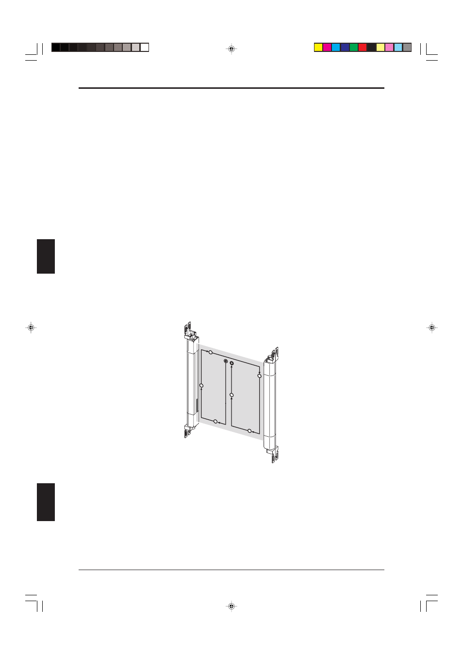
Move the test piece for detection confirmation as illustrated in the figure below.
Star
t
Stop
4. Operation Test with the Machine Operating
This test confirms that the machine stops its operation.
❏
Place the test piece in the detection zone or protection zone of the SL-CHS. It is recommended to
try three locations: near the transmitter, near the receiver, and the central area of the detection
zone. The machine must stop by the detection of the test piece.
❏
The machine must remain stopped as long as the test piece is in the detection zone.
❏
The machine will not operate when the SL-CHS Series power supply has been interrupted.
❏
The overall response time of the machine, including the response time of the SL-CHS and the time
it takes for the machine to stop, must be shorter than the overall response time T used in the
calculation of safety distances (
➮ See “2-2 Safety Distances” (page 2-5)).
4-2